The fourth power of the diameter decides everything, and the metal in the middle is barely working. This polar moment of inertia simulator is a free interactive lab built to make both of those visible: pick an outer diameter, bore the middle out, load it and choose a metal, then watch which readings move and which refuse to. On arrival the four cards answer 3.835 cm^4, 97.785 MPa, 5.652 deg/m and 1.0000x.
The second of those is the one to watch, because its sub-line is a verdict rather than a figure. It reads ok, 39.1% of yield here and OVER by 1.01x -- would have failed on the turbine preset, and the card itself changes appearance when it does. That reference is one published sample calculation’s assumed yield for the steel of its own example shaft, and measured against it 1,230 of the 3,072 reachable settings are not surviving shafts at all.
Polar Moment of Inertia Simulator
One circular shaft, end-on and along its length. Set the outer diameter, the bore, the torque and the material, then read the section’s J in m^4, how hard the surface is working and how far the shaft twists per metre. J goes as the fourth power of the diameter and does not depend on the material at all — only the twist does.
Load a Real Shaft
Each button writes the four sliders and nothing else; the simulation does every calculation itself, exactly as it would if you had dragged them. There is no mode to pick and no animation to wait for, so each one lands on a finished state immediately.
Press the first and then the second if you only press two. They are the same steel bar carrying the same torque, and the only thing that moves between them is how much of the middle is missing.
Pick one of the five shafts above, or drag the four sliders yourself.
What Is the Polar Moment of Inertia Lab Simulator?
The polar moment of inertia lab simulator is a free interactive physics lab that runs in your browser, with nothing to install and no sign-up. One round shaft is drawn twice over, end-on as a section and side-on along a metre of its length, and the panel beside it answers four things: what the section is worth, how hard its skin is working, how far it winds up, and whether it is still a shaft.
Four ladders drive it and none of them is a free-typed number. Outer diameter D steps through eight rungs from 6 mm to 400 mm, Bore, as d / D through eight from solid to bore 0.90 D, Applied torque T through eight from 1 N.m to a turbine shaft, and Material through six names. That is 3,072 reachable states, which is why any reading quoted about this lab can be landed on exactly rather than approached.
Four cards carry the answer and each has a sentence under it. Polar moment of inertia is the section property itself, and its sentence insists the material never enters it. Shear stress at the surface is the skin working, and its sentence is a verdict rather than a number.
Twist per metre is the only card a material can move. Stiffness per unit of material is the one that argues for boring the middle out.
The lab opens on a 25 mm solid steel shaft at 300 N.m, where those four read 3.835 cm^4, 97.785 MPa, 5.652 deg/m and 1.0000x. A compact grid under them adds six more readings, which at that opening state are 1.0000 of the solid polar moment kept, 1.0000 of the area kept, 0 Pa at the bore wall, 48.892 MPa at mid-radius, 3.041 kN.m^2 of torsional rigidity and 25.000 mm for the solid shaft with the same J.
Shear stress at the surface is the card to watch, because its sentence is where this lab is honest. It reads ok, 39.1% of yield on the opening shaft and OVER by 28.29x -- would have failed on a 6 mm shank carrying the same 300 N.m, and the card itself changes colour when it says so. The 250 MPa it compares against is one published sample calculation’s assumed yield for the steel of its own example shaft, not a property of steel; measured against it, 1,230 of the 3,072 states the four sliders reach are not surviving shafts at all. The arithmetic stays linear and goes on printing numbers for every one of them.
Stiffness per unit of material is the reading worth slowing down for. Bore a shaft out and the polar moment keeps 1 - k^4 of its solid value while the metal in the face keeps only 1 - k^2, so the gain per unit of material is exactly 1 + k^2 - 1.6400x at an 80 per cent bore, where the section holds 0.5904 of the stiffness on 0.3600 of the metal. The honest other half is in the stress card beside it, which rises from 97.785 MPa to 165.625 MPa on that same shaft.
Only the twist knows what the shaft is made of. Hold the opening state and walk the material slider and the first two cards do not move at all: the polar moment stays 3.835 cm^4 and the surface stress stays 97.785 MPa in every one of the six, while the twist runs from 5.652 deg/m in steel to 17.577 deg/m in aluminium and 3830.876 deg/m in polyethylene. Those six shear moduli are the source’s own tabulated typical values at room temperature, and the slider prints the attribution beside each one.
The drawing is three labelled bands. The top band is the section end-on, shaded by shear stress and hatched where the bore has taken metal away, with a scale bar in millimetres because the diameter ladder runs from 6 mm to 400 mm, a factor of 66.667 that the panel’s own strip rounds to 67. The middle band is the same shaft over one metre with a line along the surface facing you, and its caption says what scale the twist is drawn at, because most of the grid is either far too small or far too large to draw truthfully. The bottom band is one shared logarithmic axis for the polar moment, nine decades wide with a tick at every one, and it measures no length at all.
| Control | Range | Step, default and what it moves |
|---|---|---|
| Outer diameter D | 6 to 400 mm | a ladder of 8 fixed rungs - 6, 10, 17, 25, 30, 50, 100 and 400 mm - so the slider steps 1 index at a time and opens on rung 3, where the label reads "25 mm". It is the control that matters most, because the polar moment goes as the fourth power of it: the 25 mm rung reads 3.835 cm^4 and the 50 mm rung 61.359 cm^4, exactly 16 times, while the twist falls by exactly 16 and the surface stress by exactly 8 |
| Bore, as d / D | solid to 0.9 | a ladder of 8 fixed rungs - solid, then 0.2, 0.4, 0.5, 0.6, 0.7, 0.8 and 0.9 of the outer diameter - stepping 1 index at a time and opening on rung 0, where the label reads "solid". The label prints a word at rung 0 and a ratio such as "bore 0.80 D" after it, never a bore in millimetres, because that figure would be arithmetic on two ladders. Boring out is the only way to move the fourth card |
| Applied torque T | 1 N.m upward | a ladder of 8 fixed rungs from 1 N.m to the 3.18310e+6 N.m a 1000 megawatt set makes at 50 hertz, stepping 1 index at a time and opening on rung 4, where the label reads "300 N.m". It scales the stress and the twist in exact proportion and never touches the polar moment or the stiffness gain, because neither of those two knows anything about the load |
| Material | 6 materials | a ladder of six names - steel, iron, copper, titanium, aluminium and polyethylene - stepping 1 index at a time and opening on rung 0, where the label reads "steel" over the sub-line "shear modulus 79.3 GPa, a published room-temperature value". It moves the twist card and the torsional rigidity row and nothing else at all: the polar moment and the surface stress are byte-identical across all six |
| Reset | one button | restores the opening state - a 25 mm solid steel shaft at 300 N.m - and replays the settle, so the scene is drawn in rather than cut to. That state reads 3.835 cm^4 for the section, 97.785 MPa at the surface over "ok, 39.1% of yield", 5.652 deg/m of twist and 1.0000x per unit of material, and nothing is left animating once it has landed. There is no run button and no animation anywhere in this lab |
How to Use the Simulator
- Read the four cards before you touch anything. They are already answering for a 25 mm solid steel shaft at 300 N.m: Polar moment of inertia
3.835 cm^4, Shear stress at the surface97.785 MPa, Twist per metre5.652 deg/mand Stiffness per unit of material1.0000x. - Read the sentence under each card, because that is where the panel shows its hand. They read
pi (D^4 - d^4) / 32 -- the material never enters it,ok, 39.1% of yield,T L / (J G); double the diameter and this falls by exactly 16andexactly 1 + k^2; a solid shaft is the baseline. - Move Outer diameter D one rung right, from 25 mm to 30 mm. The first card goes to
7.952 cm^4and the stress card falls to56.588 MPa. Two rungs further, at50 mm, they are61.359 cm^4and12.223 MPa— sixteen times and one eighth of the 25 mm readings, exactly. - Put the diameter back and drag Bore, as d / D instead. At
bore 0.80 Dthe first card drops to2.264 cm^4, the fourth climbs to1.6400x, and the grid row for the bore wall comes alive at132.500 MPawhere it had been printing0 Pa. - Watch the stress card while you do that. It goes up, from
97.785 MPato165.625 MPa, because the same torque now rides on a smaller section. Boring a shaft out buys stiffness per unit of metal and charges for it at the skin. - Now move Material through all six names. The first two cards do not move at all. The twist card runs
5.652 deg/m,8.537 deg/m,10.027 deg/m,10.826 deg/m,17.577 deg/mand3830.876 deg/m, and the torsional rigidity row moves with it. - Push Applied torque T to its top rung. At
3.18310e+6 N.mon a 25 mm shaft the stress card reads1037.529 GPaoverOVER by 4150.12x -- would have failed, and the card changes appearance. The first card has not moved off3.835 cm^4, because the section does not know what you hung on it. - Look at the top band whenever the bore is not zero. The shading is a straight ramp from nothing on the axis out to the surface, and the hatched disc is the metal that has gone. The grid row for mid-radius is exactly half the surface figure on every setting, which is that ramp in one number.
- Read the caption under the middle band before you believe the twist. It states the factor the angle is drawn at, so a clause such as
twist shown at 10xmeans the drawn angle is ten times the real one, andtwist too small to drawmeans the line beside the dashed one is straight. - Press Reset when you have finished. It puts the four sliders back to
25 mm,solid,300 N.mandsteel, and replays the opening settle so the scene is drawn in rather than cut to.
Dragging is the right way to find out which readings move together and a poor way to land on a particular state, because all four controls step by whole rungs. The five preset buttons above exist for that reason, and the written polar moment of inertia guide is where the argument is made from scratch and the problems are worked with every step shown.
One thing this panel cannot do is take a diameter, a bore or a torque that is not on a rung, and the two inverse questions are beyond it altogether. The polar moment of inertia calculator takes typed figures, and it will run the relation backwards as well: the outer diameter behind a stiffness you need, or the largest bore that still leaves it.
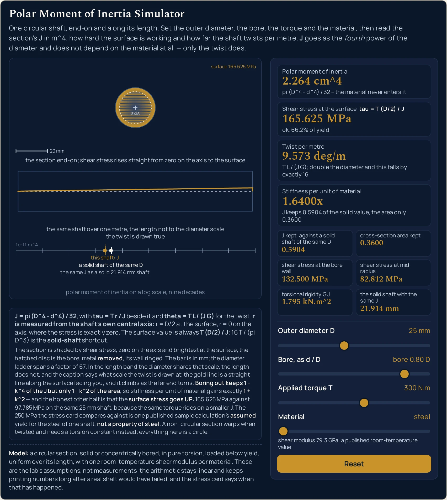
2.264 cm^4 while the fourth card reads 1.6400x, and the stress card has gone the wrong way, to 165.625 MPa. The band text is what the drawing paints at this page’s own width; it shortens on a narrow column, band by band.Worked Example: The Same Shaft, Solid and Bored to 80 Percent
Nothing in the tables below was worked out here. Each column is a setting the lab was put into through its own sliders and then read back from, cell by cell, so every string in them is the panel’s own. The first table is the pair this section is named after.
One: one bar, one torque, and the middle taken out of it
Press A 25 mm solid steel shaft at 300 N.m and then The same shaft bored out to 80 percent. Only the bore slider moves between them, so the four control rows are the same except one. This table is transposed, because the comparison worth making runs down a column.
| Panel reading | Solid | Bored to 80 per cent |
|---|---|---|
| Outer diameter D | 25 mm | 25 mm |
| Bore, as d / D | solid | bore 0.80 D |
| Applied torque T | 300 N.m | 300 N.m |
| Material | steel | steel |
| what the material slider adds | shear modulus 79.3 GPa, a published room-temperature value | shear modulus 79.3 GPa, a published room-temperature value |
| Polar moment of inertia | 3.835 cm^4 | 2.264 cm^4 |
| what that card is made of | pi (D^4 - d^4) / 32 -- the material never enters it | pi (D^4 - d^4) / 32 -- the material never enters it |
| Shear stress at the surface | 97.785 MPa | 165.625 MPa |
| the verdict beside it | ok, 39.1% of yield | ok, 66.2% of yield |
| Twist per metre | 5.652 deg/m | 9.573 deg/m |
| what the twist follows | T L / (J G); double the diameter and this falls by exactly 16 | T L / (J G); double the diameter and this falls by exactly 16 |
| Stiffness per unit of material | 1.0000x | 1.6400x |
| the exact trade | exactly 1 + k^2; a solid shaft is the baseline | J keeps 0.5904 of the solid value, the area only 0.3600 |
| J kept, against a solid shaft of the same D | 1.0000 | 0.5904 |
| cross-section area kept | 1.0000 | 0.3600 |
| shear stress at the bore wall | 0 Pa | 132.500 MPa |
| shear stress at mid-radius | 48.892 MPa | 82.812 MPa |
| torsional rigidity G J | 3.041 kN.m^2 | 1.795 kN.m^2 |
| the solid shaft with the same J | 25.000 mm | 21.914 mm |
Three rows move in the direction a reader expects and one does not. The section falls, the twist rises and the fourth card rises; the stress card rises too, from 97.785 MPa to 165.625 MPa. That last one is half the lesson of this page, and leaving it out would turn a trade into a free gift.
Read the two kept-ratio rows together. The section keeps 0.5904 of its solid value while the metal in the face keeps only 0.3600, and the fourth card is those two divided: 1.6400x. Nothing in that sentence mentions steel, and nothing in it would change if the bar were aluminium.
The bore-wall row is the one to look at twice. It prints the literal 0 Pa in the solid column, because on a solid shaft the bore wall is the axis, where the radius is nothing. Bored to 80 per cent it reads 132.500 MPa, which is eight tenths of the surface figure, exactly as a straight ramp demands.
Two: the five shafts the buttons load
These are the presets with the readings they produce. Read the stress and verdict columns across: four of the five sit under the reference and the last one does not, on a shaft that was sized against it.
| Preset | Outer diameter | Bore | Torque | Material | Polar moment | Surface stress | Against the published yield | Twist per metre | Stiffness per unit of material |
|---|---|---|---|---|---|---|---|---|---|
| A 25 mm solid steel shaft at 300 N.m | 25 mm | solid | 300 N.m | steel | 3.835 cm^4 | 97.785 MPa | ok, 39.1% of yield | 5.652 deg/m | 1.0000x |
| The same shaft bored out to 80 percent | 25 mm | bore 0.80 D | 300 N.m | steel | 2.264 cm^4 | 165.625 MPa | ok, 66.2% of yield | 9.573 deg/m | 1.6400x |
| Double the diameter, one sixteenth the twist | 50 mm | solid | 300 N.m | steel | 61.359 cm^4 | 12.223 MPa | ok, 4.9% of yield | 353.257 mdeg/m | 1.0000x |
| The same solid shaft in aluminium | 25 mm | solid | 300 N.m | aluminium | 3.835 cm^4 | 97.785 MPa | ok, 39.1% of yield | 17.577 deg/m | 1.0000x |
| A 1000 MW turbine shaft at 50 Hz | 400 mm | solid | 3.18310e+6 N.m | steel | 251327.412 cm^4 | 253.303 MPa | OVER by 1.01x -- would have failed | 915.081 mdeg/m | 1.0000x |
Rows one and three are the fourth power with nothing hidden in it. Same steel, same torque, and the diameter doubled from 25 mm to 50 mm: the section goes from 3.835 cm^4 to 61.359 cm^4 and the twist from 5.652 deg/m to 353.257 mdeg/m. Those are exactly sixteen times and exactly one sixteenth, and the preset title is that claim.
Rows one and four differ by one slider and three readings. The polar moment is the same string, the surface stress is the same string, and the verdict is the same string; only the twist changes, from 5.652 deg/m to 17.577 deg/m. That single comparison is the headline claim of this subject made testable.
Row five is the honest one. A 400 mm shaft at the torque a 1000 megawatt set makes at 50 hertz reads 253.303 MPa, flagged OVER by 1.01x -- would have failed, on a shaft whose published size was chosen against that very figure. The reason is rounding, and it is picked apart further down this page.
Formula and Symbol Reference
The band at the head of this page carries the section property with the stress relation beside it, because the first on its own is what makes this quantity confusing. Every reading on the panel is one of those two relations, the twist that follows from them, or a ratio between two sections.
The symbol column below uses the panel’s own names, spelled the way the lab’s own strip spells them in plain ASCII. Where the figure in the torque slider comes from — a force and a lever arm — is the torque guide; and for which of the two letters belongs to which quantity, the physics symbols guide keeps the list.
| Symbol or readout | Meaning | SI unit | In this lab |
|---|---|---|---|
| J | The polar moment of inertia of the cross-section: the integral of the squared distance from the central axis over the area. It is what the lab answers, it is a property of the shape alone, and it is never something you set | metre to the fourth power | the first card, to three decimals in the largest unit that keeps the number at or above one, so it carries mm^4, cm^4 or m^4 and the unit changes under you as you slide. The opening shaft reads 3.835 cm^4; across the whole grid the smallest is 43.756 mm^4 and the largest 251327.412 cm^4, which is why nothing the sliders reach falls off either end of the bottom band. |
| D | The outer diameter, measured right across the shaft. Every result on the panel turns on it, because the integral puts the fourth power of it into the answer | metre (m), shown in millimetres | a ladder of eight rungs, 6 mm to 400 mm, opening on 25 mm. The slider steps one index at a time, so no intermediate diameter exists. At 6 mm the first card reads 127.235 mm^4 and the stress card 7.074 GPa; at 400 mm they read 251327.412 cm^4 and 23.873 kPa, with everything else held at the default. |
| d / D | How much of the middle has been bored out, as the bore diameter divided by the outer diameter. It is a diameter over a diameter, never a radius and never a wall thickness | dimensionless ratio | a ladder of eight rungs, opening on solid and running through bore 0.20 D to bore 0.90 D. The label prints a word at the first rung and a ratio after it, and never a bore in millimetres. At bore 0.90 D the section is down to 1.319 cm^4 and the fourth card is up at 1.8100x. |
| T | The applied torque, twisting the shaft about its own axis. It scales the stress and the twist in exact proportion and leaves the section property untouched | newton metre (N.m) | a ladder of eight rungs, 1 N.m to 3.18310e+6 N.m, opening on 300 N.m. The top rung prints in exponential form rather than as a seven-digit integer. At the bottom rung the stress card reads 325.949 kPa and at the top 1037.529 GPa, while the first card does not move off 3.835 cm^4 at either. |
| r | How far out from the shaft’s centreline a stress is being quoted at. Read it as a bore radius, or as a depth inwards from the skin, and every stress figure on the panel comes out wrong — which is the single most likely reader error in this subject | metre (m) | not a control. The panel samples it at three places: the bore wall, mid-radius and the surface. On the opening shaft those read 0 Pa, 48.892 MPa and 97.785 MPa, and the middle one is exactly half the last on every state the sliders reach. |
| tau | The shear stress: how hard the metal is working at the radius it is quoted at. It is exactly proportional to that radius, so it is exactly zero on the axis and largest at the surface | pascal (Pa) | the second card for the surface value, with two of the grid rows for the bore wall and mid-radius, to three decimals in the largest unit at or above one. Over the grid it runs from 79.577 Pa to 218239.979 GPa. Its sub-line is a verdict rather than a number, and the card itself changes appearance once that verdict begins with OVER. |
| G | The shear modulus of the material: how stiff it is against shearing rather than against stretching. It is the only place a material enters this lab at all | pascal (Pa), shown in gigapascals | the material slider sub-line, which prints a sentence such as shear modulus 79.3 GPa, a published room-temperature value. Six names are offered and the six figures are the source’s own tabulated typical values at room temperature: steel 79.3 GPa, iron 52.5 GPa, copper 44.7 GPa, titanium 41.4 GPa, aluminium 25.5 GPa and polyethylene 0.117 GPa. |
| theta | The angle the shaft winds up through, reported per metre of length because the twist is exactly proportional to the length. It is the only reading on the panel that knows what the shaft is made of | radian, shown in degrees per metre | the third card, to three decimals in degrees, milli-degrees, micro-degrees or nano-degrees per metre. The opening shaft reads 5.652 deg/m. The widest readings the four sliders reach are 287.481 ndeg/m and 35624586017.214 deg/m, which is eighteen distinct decades and the reason the middle band states a drawing scale. |
| 1 + k^2 | The stiffness per unit of material of a bored section against a solid one of the same outer diameter. It is the sharpest result in the lab and it is exact | dimensionless ratio | the fourth card, to four decimals with an x after it. It is 1.0000x on every solid section and climbs rung by rung to 1.8100x at bore 0.90 D. Its sentence has two shapes: a baseline sentence at solid, and a kept-ratios sentence at each of the seven hollow rungs, no two of which read alike. |
| G J | The torsional rigidity: how much torque the shaft needs per radian of twist per metre. It is the one reading in which the material stands beside the shape | newton metre squared | the fifth grid row, to three decimals. It reads 3.041 kN.m^2 on the opening shaft and 977.913 N.m^2 on the same shaft in aluminium. At the four corners of the grid it runs from 5.119 mN.m^2 to 199.303 MN.m^2. |
| the equivalent solid shaft | The plain round bar that would have exactly the same polar moment as the section on screen. On a solid shaft it is the shaft itself, which is the identity made visible | metre (m), shown in millimetres | the sixth grid row, to three decimals. 25.000 mm on the opening shaft, 21.914 mm once it is bored to 80 per cent, 19.145 mm at bore 0.90 D. On all 64 solid settings it equals the outer diameter to the last bit. |
If you read one row twice, make it the fifth. Every stress figure the panel prints is quoted at a radius counted outward from the centreline, which puts the surface reading at D/2 and the axis reading at nothing at all. Nearly every wrong answer in this subject is that one length taken from the wrong place.
Reading the Diagram: a Stress Ramp, a Twisted Line and a Log Axis
The drawing is laid out as three bands and each band caption strip is reserved before anything is placed in it, so no part of the picture is ever painted across another. The top band carries the section, the middle band carries the twist, and the bottom band carries the one axis that is shared.
| Part of the drawing | What it paints | What it does not claim |
|---|---|---|
| the section band | The top band. One circular section seen end-on, shaded by shear stress and brightest at the surface, with the bore drawn as a hatched disc of removed metal and its wall ringed, a cross on the central axis, the surface marked with the same stress string the second card prints, and a labelled scale bar in millimetres | it does not show a ring of anything. The shading is a ramp that starts at exactly zero on the axis, and the caption keeps that clause on screen at every width, because the ramp is the whole reason a bored shaft loses so little. The scale bar is there because the diameter ladder runs from 6 mm to 400 mm, a factor of 66.667 that the panel’s own strip rounds to 67, so no two settings may be compared by eye |
| the length band | The middle band. The same shaft side-on over one metre, with a dashed straight reference line along the surface facing you and the twisted line beside it, climbing as the far end turns, and a radial spoke at the loaded end | it does not draw the length to the same scale as the diameter, and it says so on its first caption line. One metre against a 25 mm shaft is forty to one, and drawing that honestly would leave a hairline. It also never draws an angle without stating what scale it is at |
| the log axis band | The bottom band. One shared logarithmic axis for the polar moment, anchored on its decades over nine of them with a tick at every decade, carrying markers for this section, for the solid shaft of the same outer diameter, and for the solid shaft with the same polar moment | it does not measure a length. The band above it measures a length and this one measures a fourth power of one, so nothing horizontal in the two means the same thing. Every setting the sliders reach lands inside the nine decades, so no marker is ever clamped at either end |
| what the picture is for | Seeing the shape of the result. The ramp, the gap between the twisted line and the dashed one, and the distance between two markers on a log axis are the three arguments of this lab drawn rather than stated | it is not evidence. The drawing is made from the numbers the sliders set, so it shows the shape of the model rather than discovering it. Where a real shaft departs from the model is set out below, and none of it is visible in the picture at all |
The ramp starts at exactly zero and that is the point of the whole band. Shear stress is the torque times the distance from the axis divided by the section, so it is strictly proportional to that distance: nothing on the axis, half the surface value at mid-radius, and the bore ratio times the surface value at the bore wall. The panel prints all three as numbers, so the picture can be checked rather than trusted.
The middle band never draws an angle without saying what scale it is at. The twist the sliders can reach runs from 287.481 ndeg/m to 35624586017.214 deg/m, which is eighteen distinct decades, so a true drawing is impossible across almost all of it. The lab magnifies or reduces by a power of ten to bring the angle into a band it can draw, and the caption carries the factor.
There are fifteen of those clauses, not two. They cover eighteen distinct decades of twist between them: one for an angle drawn true, thirteen magnifying and reducing powers of ten (four up and nine down), and twist too small to draw on 294 of the 3,072 settings, where the line beside the dashed one is simply straight. No setting anywhere draws a twisted line without a clause.
The bottom band is nine decades because it has to hold everything the sliders can reach. The smallest polar moment they produce is 43.756 mm^4 and the largest 251327.412 cm^4, and every one of the nine decades carries a tick. The three markers on it are this section, the solid shaft of the same outer diameter, and the solid shaft with the same polar moment — and on a solid setting all three land together.
The Physics: Why the Fourth Power, and Why Hollow Wins
Leave the panel on the opening shaft and ask what the outer metal is doing that the core is not. Two things grow with the radius at the same time: metal further out has to shear through a greater distance for the same wind-up, and whatever it pushes back with acts on a longer arm about the centre. Multiply those together and each ring contributes as the square of its radius, which is why the defining integral weights area by that square — and why, taken over a disc, it collapses onto the fourth power of the diameter.
Every consequence is in that exponent. Double the diameter and the section is multiplied by exactly sixteen, so the twist falls by sixteen and the surface stress by eight, whatever the torque, the length or the metal. Press the third preset and read it off: 3.835 cm^4 becomes 61.359 cm^4, 5.652 deg/m becomes 353.257 mdeg/m, and 97.785 MPa becomes 12.223 MPa.
The same exponent is why hollow wins. Bore a concentric hole of ratio k and the section keeps exactly 1 - k^4 of its solid value while the metal in the face keeps only 1 - k^2, and the ratio of those two is exactly 1 + k^2. The bore ladder below is that identity walked rung by rung.
| Bore setting | Polar moment | Surface stress | Against the published yield | Twist per metre | Stiffness per unit of material | Polar moment kept | Area kept | Stress at the bore wall | Equivalent solid shaft |
|---|---|---|---|---|---|---|---|---|---|
| solid | 3.835 cm^4 | 97.785 MPa | ok, 39.1% of yield | 5.652 deg/m | 1.0000x | 1.0000 | 1.0000 | 0 Pa | 25.000 mm |
| bore 0.20 D | 3.829 cm^4 | 97.942 MPa | ok, 39.2% of yield | 5.661 deg/m | 1.0400x | 0.9984 | 0.9600 | 19.588 MPa | 24.990 mm |
| bore 0.40 D | 3.737 cm^4 | 100.354 MPa | ok, 40.1% of yield | 5.801 deg/m | 1.1600x | 0.9744 | 0.8400 | 40.142 MPa | 24.838 mm |
| bore 0.50 D | 3.595 cm^4 | 104.304 MPa | ok, 41.7% of yield | 6.029 deg/m | 1.2500x | 0.9375 | 0.7500 | 52.152 MPa | 24.600 mm |
| bore 0.60 D | 3.338 cm^4 | 112.345 MPa | ok, 44.9% of yield | 6.494 deg/m | 1.3600x | 0.8704 | 0.6400 | 67.407 MPa | 24.147 mm |
| bore 0.70 D | 2.914 cm^4 | 128.681 MPa | ok, 51.5% of yield | 7.438 deg/m | 1.4900x | 0.7599 | 0.5100 | 90.077 MPa | 23.342 mm |
| bore 0.80 D | 2.264 cm^4 | 165.625 MPa | ok, 66.2% of yield | 9.573 deg/m | 1.6400x | 0.5904 | 0.3600 | 132.500 MPa | 21.914 mm |
| bore 0.90 D | 1.319 cm^4 | 284.341 MPa | OVER by 1.14x -- would have failed | 16.435 deg/m | 1.8100x | 0.3439 | 0.1900 | 255.907 MPa | 19.145 mm |
Divide the last two ratio columns into each other on any row and the sixth column falls out. At bore 0.80 D that is 0.5904 over 0.3600, which the panel prints as 1.6400x. The reason is the ramp: the metal near the axis was barely carrying anything, so removing it costs the fourth power of the ratio and saves only the square.
And the honest other half is in the third column. The surface stress climbs every rung, from 97.785 MPa solid to 284.341 MPa at bore 0.90 D, where the verdict finally flips to OVER by 1.14x -- would have failed. The gain is per unit of material, never per shaft, and the bottom rung of that ladder is a section that has stopped being a shaft.
The sharpest result on the panel needs no material at all, and the material slider is how you prove it. Hold the opening shaft and walk all six names: the first two cards print the same two strings every time.
| Material | Published shear modulus | Polar moment | Surface stress | Twist per metre | Torsional rigidity |
|---|---|---|---|---|---|
| steel | 79.3 GPa | 3.835 cm^4 | 97.785 MPa | 5.652 deg/m | 3.041 kN.m^2 |
| iron | 52.5 GPa | 3.835 cm^4 | 97.785 MPa | 8.537 deg/m | 2.013 kN.m^2 |
| copper | 44.7 GPa | 3.835 cm^4 | 97.785 MPa | 10.027 deg/m | 1.714 kN.m^2 |
| titanium | 41.4 GPa | 3.835 cm^4 | 97.785 MPa | 10.826 deg/m | 1.588 kN.m^2 |
| aluminium | 25.5 GPa | 3.835 cm^4 | 97.785 MPa | 17.577 deg/m | 977.913 N.m^2 |
| polyethylene | 0.117 GPa | 3.835 cm^4 | 97.785 MPa | 3830.876 deg/m | 4.487 N.m^2 |
Two columns are frozen and two are not. The polar moment and the surface stress are byte-identical down all six rows, because neither contains a material; the twist and the torsional rigidity move with the modulus, which is the only place a material enters. Those six modulus figures are the source’s own tabulated typical values at room temperature, and none was checked independently here.
One bridge is worth stating, and then it stops. The mass moment of inertia of a uniform shaft is exactly this quantity multiplied by a density and a length, which is why one is in metres to the fourth power and the other in kilogram metres squared. That is an identity rather than a figure: neither source here gives a density, so no kilogram metre squared number appears on this page at all. The quantity itself, for nine common shapes, belongs to the moment of inertia guide and to the moment of inertia simulator.
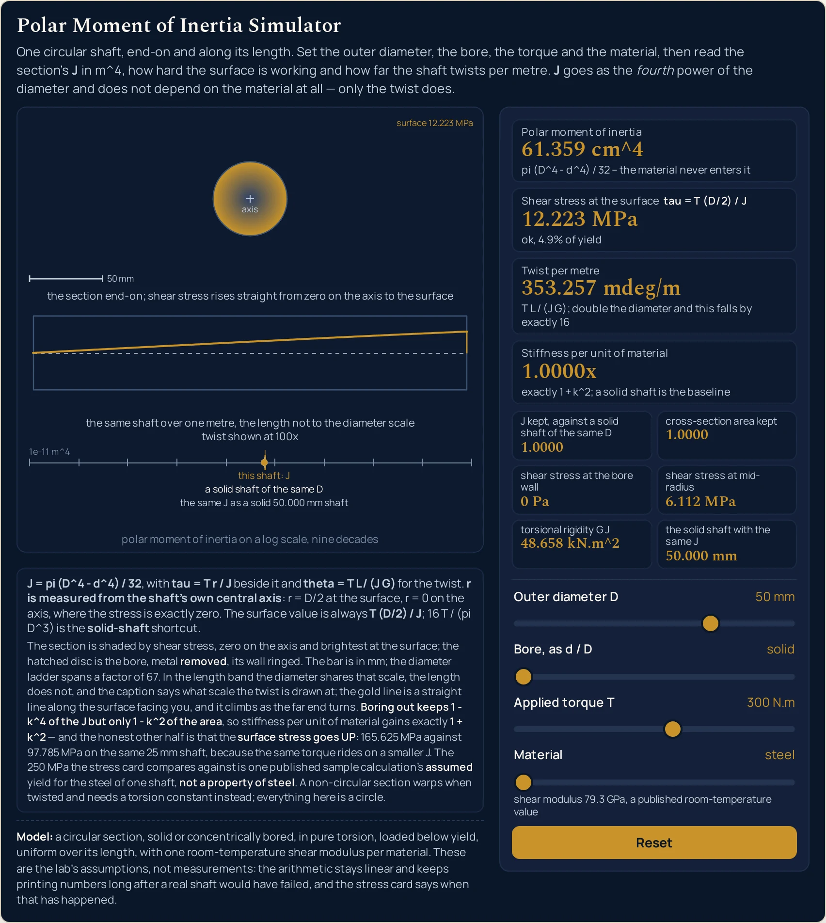
300 N.m on 50 mm instead of 25 reads 61.359 cm^4 and 353.257 mdeg/m — sixteen times and one sixteenth of the first preset, to the last digit. Compare the gap between the twisted line and the dashed one here with the first figure, remembering that the two captions state different drawing scales.Where It Breaks Down
Every state the four sliders can reach is answered, and the arithmetic is not where this lab can let you down. What it cannot do is model a real shaft, and what it refuses to do is treat its own idealisations as facts. The first item below is the one that matters more than all the others put together.
- The model never notices that the shaft has broken
- Read this one before any of the others. Torque and stress stay in strict proportion here however large either grows, so the panel answers settings that no piece of metal would survive. Measured against the 250 MPa reference, 1,230 of the 3,072 states the sliders reach are past it — 40.04 per cent of the grid — and the worst corner prints
218239.979 GPaof shear stress. The stress card says so state by state and changes appearance when it does; the polar moment card never will, because a property of the shape is simply indifferent to whether the metal held. - The 250 MPa is an assumption about one shaft, not a property of steel
- It is the figure a published sample calculation states for the steel of its own example shaft, inside its own sizing arithmetic, and this lab uses it only as a fixed reference to measure a stress against. Any actual component arrives with a certificate for the metal it was cut from, a heat treatment history and a safety factor somebody chose on purpose. Nothing on this page is a design allowable, and the percentages beside the stress card are comparisons rather than verdicts on anybody’s part.
- The six shear moduli are published typical values, not properties of your metal
- They come from a table headed as typical values at room temperature, each carrying its own citation marker in the source, and none of them was independently checked in this slot. No temperature dependence, no alloy and no heat treatment is claimed for any of them. They matter only for the twist card and the torsional rigidity row, and the material slider prints the attribution underneath so that it travels with the number. The stretching modulus is a different constant again, and the Young’s modulus calculator is where that one lives.
- A published rounding is not an exact figure, and the turbine preset proves it
- The sizing calculation behind that preset computes a radius of 0.200877 m and quotes 0.200 m, or a diameter of 400 mm; its factor-of-five case quotes 0.343 m and 690 mm, where the literal diameter is 0.6870 m and its own radius doubles to 686 mm. Because stress goes as one over the radius cubed, rounding the radius down pushes the stress up: the 400 mm shaft reads
253.303 MPa, which is 1.3212 per cent above the 250 MPa it was sized against. It is not a safe shaft, it is a rounded one, which is why the source then applies a factor of safety of five. - Everything on this panel is a circle
- Twist a section that is not round and it warps out of its own plane, so this quantity stops being the torsional constant and a torsion constant takes over the job. The cleared source states that outright, in a sentence quoted whole in the references below and paraphrased in one line under the drawing. Nothing here offers a figure for a square bar, a splined hub or a keyed shaft, because nothing here sources one.
- Twisting, and nothing else at all
- Nothing in this model is bent, stretched or pushed sideways, and the shaft itself has no keyway cut into it, no shoulder, no press fit and no change of diameter along its length. Features like those are where shafts actually break, almost never in the plain barrel between them. No figure is offered for that here, for one reason: a stress concentration factor is precisely what neither cleared source carries, and a number made up to fill the hole would conceal it instead of marking it.
- Everything is per metre, and the bore is on the axis
- There is no length slider, because the twist is exactly proportional to the length and a per-metre figure is therefore the general one. There is no eccentric bore either, no cross-drilling and no seam: the hole is assumed concentric and smaller than the shaft, which is what makes the kept-ratio rows exact. A section with any of those features is a different calculation this lab does not do.
- This shear stress is not the shear stress in a fluid
- The symbol is shared and the quantity is not. Here it is an elastic shear stress in a twisted solid, fixed by a geometry and a torque; in a fluid it is set by a velocity gradient and a viscosity, and nothing on this page applies to it. The viscosity guide is where that other one lives, and the viscosity simulator is the panel for it.
- The sliders are ladders, and the lab runs one way only
- All four controls step by whole rungs, so the lab reaches 3,072 states and nothing in between. It also runs forwards only: you set a section and a load and read what follows. The polar moment of inertia calculator takes typed figures and runs the relation in all three directions, including the largest bore that still leaves a stiffness you have to keep.
- Three things the drawing gives up on a narrow screen
- Below a drawn radius of 26 pixels the word marking the central axis is dropped, although the cross is still there and the caption still says the stress rises from zero on the axis. The label on the equivalent-solid marker shortens in four steps and is dropped if none fits, although its stem stays and the panel keeps the figure. And below a 160 pixel drawing the bands would begin switching off rather than drawing something unexplained. On a narrow screen take the figures from the cards, which are unaffected.
Where the Polar Moment of Inertia Is Actually Used
- Deciding whether to bore a driveshaft out
- Load The same shaft bored out to 80 percent and the whole decision is on screen in two cards. The section keeps
0.5904of its value on0.3600of the metal, so the fourth card reads1.6400x; the stress card goes from97.785 MPato165.625 MPa. Tubing wins that trade, which is why so little of a driveshaft, a bicycle spindle or an aircraft control rod is solid metal — and why the wall that is left then gets argued over on its own account. - Sizing a shaft from the stiffness it has to have
- Move the diameter slider one rung and watch how little it takes. From
25 mmto30 mmthe section goes from3.835 cm^4to7.952 cm^4, which is more than double for a fifth more diameter, and the twist falls from5.652 deg/mto2.726 deg/m. The fourth power is the cheapest lever in the whole problem, which is why it is pulled first. - Reproducing a published turboset sizing
- Load A 1000 MW turbine shaft at 50 Hz: 400 mm solid at
3.18310e+6 N.m, which is the torque a 1000 megawatt set makes at 50 hertz. Getting from a power rating to that torque is one step, since power is torque times angular speed, and the power guide is where it lives. The panel prints253.303 MPafor the rounded shaft, which is why the published calculation then applies a factor of safety. - Choosing a metal when the stiffness is already fixed
- The material slider is a specification in one card. Switch the opening shaft from steel to aluminium and the section stays
3.835 cm^4, the surface stress stays97.785 MPa, and only the twist changes, from5.652 deg/mto17.577 deg/m. If a design is limited by stress, the metal is nearly irrelevant; if it is limited by wind-up, the metal is most of the answer. - Checking a stress against a published yield figure
- The sentence under the stress card turns a section into something arguable.
310.989 MPaon a 17 mm spindle arrives withOVER by 1.24x -- would have failedattached, which is far more useful than the stress alone. The reference it is measured against is one sample calculation assumption about one shaft, so read the percentage as a comparison and never as a sign-off on a real part. - Catching a figure somebody else quoted
- The commonest practical use of this panel is as a check. Set the diameter, the bore and the torque the figure was supposedly taken at and see whether the cards agree, and if the quoted stress has no radius attached to it, the grid rows show how much room there is:
0 Paon the axis,48.892 MPaat mid-radius and97.785 MPaat the surface of one ordinary shaft. - Telling this quantity apart from the one it is named after
- Spinning a wheel or a rotor up to speed is a question about the mass moment of inertia, which cannot be answered without knowing how much metal there is and where; the moment of inertia calculator is the page for that one. There is no mass control anywhere on this panel, because the quantity it prints contains no mass at all. The two are not interchangeable, and nothing this panel displays can be turned into the other without information it was never given.
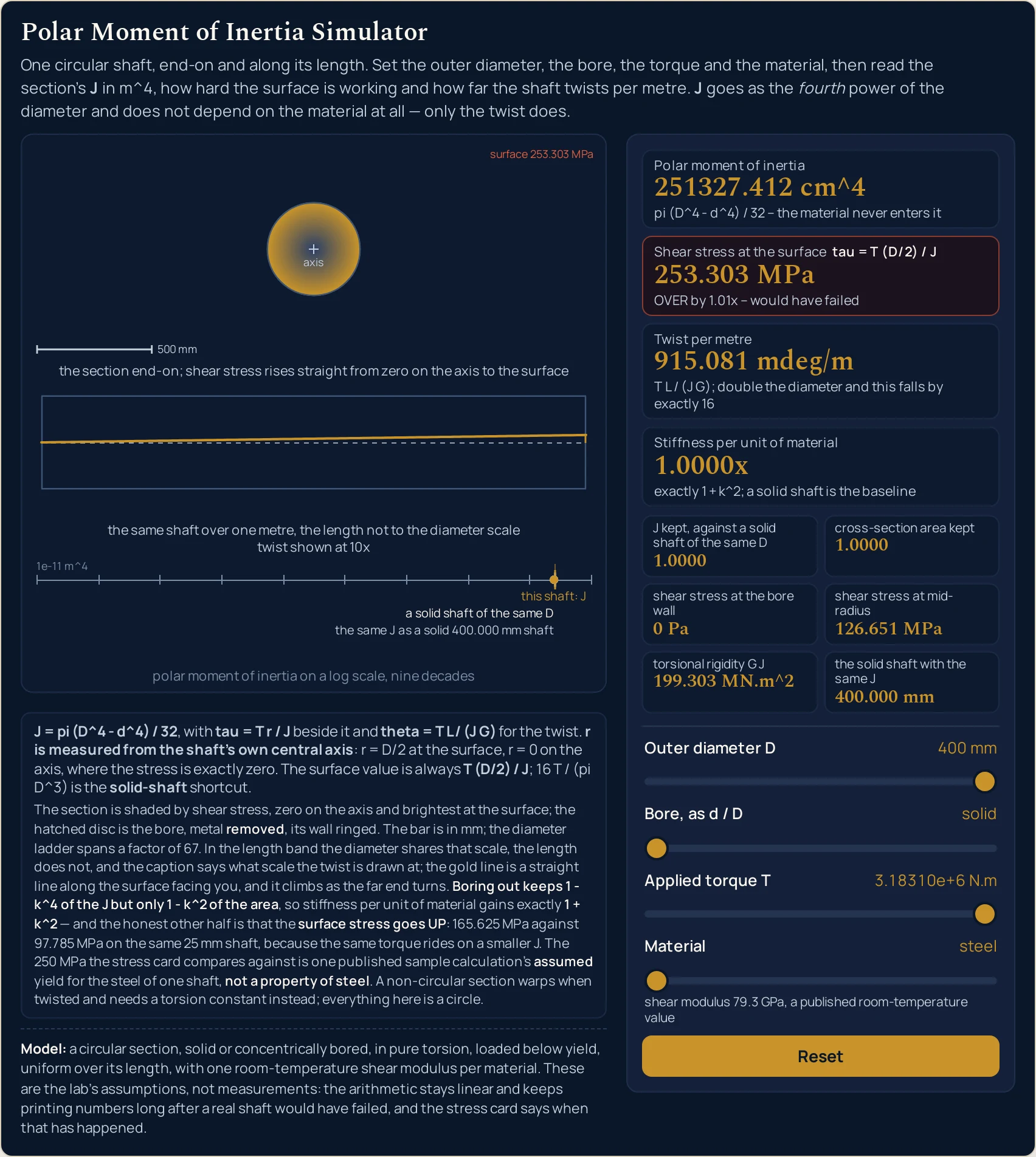
253.303 MPa over OVER by 1.01x -- would have failed, on a 400 mm shaft whose published diameter was sized against 250 MPa — the excess is the rounding of the radius, not a mistake in the arithmetic. Note how far right the markers have walked along the bottom band compared with the other two figures.Where to Go Next
A panel can put you in a state and let you move one thing at a time, and that is the end of what a panel is for. The polar moment of inertia guide is where the subject itself is written out: why the fourth power dominates, what boring a shaft out really buys and costs, and why this quantity is not the one it is named after, with the problems worked step by step.
One post sits very close to this one and is not the same thing. The moment of inertia guide owns the mass moment of inertia in kilogram metres squared, for nine common shapes, which is about how hard a body is to spin up rather than how hard a section is to twist.
Five more pick up what this lab uses but does not explain. The torque guide is the quantity on the torque slider, the moment of a force guide is the same idea under its other name, the power guide turns a turbine rating in megawatts into the figure the torque slider wants, the physics symbols guide settles which letter stands for which quantity, and the mechanics formula sheet is the one-page reference.
Six more again sit one step further out. The types of forces guide is where a shear force sits among the others, Hooke's law and the spring constant guide are the stretching half of elasticity, the equilibrium guide is what has to balance before any of this applies, the angular momentum guide is the rotating body in motion, and the viscosity guide is the other shear stress entirely.
On the tool side, the polar moment of inertia calculator takes typed diameters, bores and torques and runs the relation in all three directions, the moment of inertia calculator is the mass quantity, the torque calculator works a torque from a force and a lever arm, the Nm to ft-lb converter changes its unit, the Young’s modulus calculator is the stretching modulus, and the angular momentum calculator is the body in motion.
Six neighbouring pictures sit beside this one: the moment of inertia simulator, the torque simulator, the Hooke’s law simulator, the equilibrium simulator, the angular momentum simulator and the viscosity simulator. Beyond them there is the simulation library, an index of calculators, and the blog for everything written out at length.
Frequently asked questions
Why does the bore wall read exactly 0 Pa when the shaft is solid?
Because on a solid shaft the bore wall is the axis, where the radius is zero, and the lab returns a literal zero from a branch of its own rather than dividing. Shear stress is exactly proportional to the distance from the central axis, so the ramp in the top band starts at nothing. All 64 solid settings print the same string, 0 Pa.
Why does the stress card change colour on some settings and not others?
Because the surface stress has gone past the 250 MPa reference and the card says so without being read. That reference is one published sample calculation’s assumed yield for the steel of its own example shaft, not a property of steel. The state fires on 1,230 of the 3,072 settings the four sliders can reach, and the sub-line turns from a percentage into a sentence beginning OVER.
Why do the first two cards refuse to move when I change the material?
Because neither of them contains a material. The polar moment is an integral over a cross-section and the surface stress is the torque divided by it, so both are identical in steel, iron, copper, titanium, aluminium and polyethylene: 3.835 cm^4 and 97.785 MPa on the opening shaft in all six. Only the twist card and the torsional rigidity row move, because only those two carry a shear modulus.
What does a clause like twist shown at 10x under the middle band mean?
It means the drawn angle is ten times the real one, and the caption states the factor so the picture never claims more than it shows. The reachable twist spans eighteen distinct decades, so a true drawing is impossible almost everywhere: the lab magnifies or reduces by a power of ten to bring the angle into a band it can draw, and says twist too small to draw on 294 settings where it cannot.
Why does the fourth card say boring out gains stiffness when the stress card gets worse?
Because the gain is per unit of material and not per shaft, and the panel shows both halves at once. Bored to 80 per cent, the section keeps 0.5904 of its polar moment on 0.3600 of the metal, so the fourth card reads 1.6400x. The surface stress on that same shaft rises from 97.785 MPa to 165.625 MPa, because the same torque now rides on a smaller section.
Why do the sliders step through fixed rungs instead of moving smoothly?
Because a ladder makes every reading on this page reproducible rather than approximate. The diameter slider has eight rungs from 6 mm to 400 mm, the bore slider eight from solid to 0.9, the torque slider eight and the material slider six, which is 3,072 states and nothing between them. The companion calculator takes typed figures and runs the relation backwards as well.
Why is the bottom band nine decades wide when one shaft covers so little of it?
Because the diameter slider alone moves the polar moment by 7.296 decades, and one shared axis is the only honest way to show that. Together the sliders reach from 43.756 mm^4 to 251327.412 cm^4, a span of 7.759 decades, and no setting is ever pushed off either end of the nine-decade axis. Every one of the nine decades carries a tick, and the band measures no length at all.
What does the Reset button put back?
All four sliders, to a 25 mm outer diameter, a solid section, 300 N.m and steel. It replays the opening settle rather than cutting to it, so the scene is drawn in, and the panel lands on 3.835 cm^4, 97.785 MPa over ok, 39.1% of yield, 5.652 deg/m and 1.0000x. Nothing is left animating once it has finished.
References & formula source
- Every figure on this page is one relation read somewhere different. The polar moment of inertia of a circular section is the integral of the squared distance from the central axis over the area, which for an annulus of outer diameter D and bore d is pi times the difference of their fourth powers divided by 32, with a bore of zero giving the solid case. The shear stress at a radius is the torque times that radius divided by the polar moment, so it is exactly zero on the axis and largest at the surface. The twist is the torque times the length divided by the polar moment times the shear modulus. The relations are applied here rather than derived.
- Six things are this lab’s stated assumptions and not measurements of any shaft: the section is a circle, solid or bored concentrically; the loading is pure torsion with no bending, no axial load, no keyway and no shoulder; the material stays linear elastic below yield; the section is uniform over its length and every twist is reported per metre; each material carries one room-temperature shear modulus; and the bore is on the axis with a diameter smaller than the outer one. The panel prints that list in a fixed line under the drawing and labels it as the model rather than as a finding.
- The yield figure this lab compares against is 250 MPa, and it is the assumed yield stress of the steel used to make one particular shaft in one published sample calculation. It is not a property of steel, it is not a design allowable, and it is used here only as a fixed reference to measure a stress against. None of what would settle the question travels this far: the certificate for the metal a shaft was actually cut from, the heat treatment it actually received and the factor of safety somebody actually signed off all sit outside this lab, which is given four slider positions and nothing else.
- The arithmetic is linear elastic and it never stops, which is the honest shape of this whole subject. Measured against that 250 MPa reference, 1,230 of the 3,072 states the four sliders can reach are past it, which is 40.04 per cent of the grid, and the worst corner prints 218,239.979 GPa of shear stress. Because the surface stress carries no material in it, that fraction is a property of the diameter, bore and torque ladders alone rather than an estimate. The stress card says so state by state, and the polar moment card never will, because a property of the shape is simply indifferent to whether the metal held.
- The six shear modulus figures are the second source’s own tabulated typical values at room temperature, under its own heading, and none of them was independently checked in this slot. They are steel 79.3 GPa, iron 52.5 GPa, copper 44.7 GPa, titanium 41.4 GPa, aluminium 25.5 GPa and polyethylene 0.117 GPa. No temperature dependence, no alloy and no heat treatment is claimed for any of them, and the material slider prints the attribution beside each one so that it travels with the number. Nothing on this page except the twist and the torsional rigidity depends on them at all.
- The published sizing calculation this lab’s turbine preset comes from quotes rounded figures, and no page may treat a rounding as exact. Its radius evaluates to 0.200877 m and is quoted as 0.200 m, or a diameter of 400 mm; its factor-of-five case quotes a radius of 0.343 m and a diameter of 690 mm, where the literal diameter is 0.6870 m and the source’s own radius doubles to 686 mm. The direction of that rounding matters, because stress goes as one over the radius cubed: the rounded 400 mm shaft carries 253.303 MPa, which is 1.3212 per cent above the 250 MPa it was sized against rather than below it.
- The polar second moment can be insufficient for use to analyze beams and shafts with non-circular cross-sections, due their tendency to warp when twisted, and a torsion constant is substituted instead. Those words belong to the first cleared source, grammatical slip and all, and this lab adds nothing to them beyond one paraphrased line under its own drawing. A square bar, a splined hub or a keyed shaft therefore gets no number anywhere here, because no number for one is sourced.
- No mass, no density and no kilogram metre squared figure appears anywhere on this page, because neither source cleared for this cluster gives a density. The mass moment of inertia of a uniform shaft is exactly this quantity multiplied by a density and a length, which is why one is in metres to the fourth power and the other in kilogram metres squared. That is stated once as an identity and then stopped, and the quantity it names has its own page.
- Every figure quoted on this page is a string the simulation printed. The cluster simulation report is where those strings are recorded, and it is not a sample: it harvests all five presets with all nineteen of their readouts, both ends of all four sliders, the four corners of the grid, every one of the eight bore rungs on the anchor shaft, all six materials on it, the six-shaft comparison including both over-yield rows, all 512 diameter, bore and torque states in steel, the exact zeros, the clause the length band carried on every one of the 3,072 states, and the Reset button before and after, from a real browser against a digest-pinned file. The independent reference script, written before the simulation, runs 2,260 checks against the same relations with none failing.
- That report was regenerated from the bytes that actually ship. The simulation was edited after its first set of gate logs was written, so the first report described a file that was no longer on disk, and all six gates and the whole harvest were re-run against the shipped digest before this page was written. No preset figure moved. What changed was the drawing: the line that shows the twist was moved onto the surface facing the viewer so that its departure from straight is proportional to the angle rather than to the square of it, and the band of angles the lab is willing to draw was narrowed by a decade so that every drawn angle is visible. That defect was found by rasterising the canvas and looking at it, not by an assertion.
- Two browser engines were compared reading by reading rather than assumed to agree: the same slider positions were driven in Chrome and in Firefox and nineteen checks compared, every one passing, with the desktop height agreeing to the pixel. There is a hole in that and it is Safari. The WebKit build on the machine this was tested on will not start, so Safari was never exercised and nothing on this page is evidence about it. Touch and pointer dragging were likewise not exercised: both test harnesses drive the sliders by writing a value and dispatching an event rather than by moving a finger.
- Three limits of the drawing are recorded rather than hidden. The word marking the central axis in the top band is dropped when the drawn radius falls below 26 pixels, although the cross is still drawn and the caption still says the stress rises from zero on the axis. The label on the equivalent-solid marker in the bottom band shortens in four steps and is dropped if none of them fits, although its stem is still drawn and the panel still carries the figure. And below a 160 pixel drawing the bands would begin switching off one at a time rather than drawing something unexplained, which is narrower than any width this site is tested at.
- Further reading: Second polar moment of area — Wikipedia