How hard a round shaft is to twist needs two numbers and no material: the diameter across it and the diameter of the hole up the middle. Take the fourth power of each, subtract, multiply by π and divide by 32. This free polar moment of inertia calculator runs that in all three directions and prints the shear stress at the surface at your torque, how much stiffer per unit of metal the section is than a solid bar of the same outer diameter, and the solid bar that would be equally hard to twist. Point Solve for at J, at the outer diameter or at the bore.
The bore d is a diameter, not a wall thickness — a 30 mm shaft bored to 21 mm has a 4.5 mm wall, not 21 mm — and the r in tau = T r / J is measured from the shaft’s own central axis, so it is D/2 at the surface and 0 on the axis. The boxes accept 1e-14 to 1 m^4, 1e-4 to 2 m for the outer diameter, 0 to 2 m for the bore and 0 to 1e9 N·m; a bore at or past the outer diameter is declined rather than answered, and so is a J larger than the solid J of the diameter you gave. The yield figure the stress reading is measured against is the 250 MPa the source assumes for the steel of one particular shaft, not a property of steel.
Load a real shaft
Every button writes all four boxes in their default units, so whichever quantity the Solve for menu is pointing at, the remaining three already agree with it. The line underneath quotes back whatever the widget works out from that, so nothing in it is stored text.
Pick a shaft above, or type your own numbers.
What Is the Polar Moment of Inertia Calculator?
The polar moment of inertia calculator is a free online tool for the second moment of a round cross-section area about the shaft’s own axis: J = pi (D^4 - d^4) / 32, in metres to the fourth power. Give it any two of J, the outer diameter and the bore diameter and it returns the third in whichever unit that box was set to, with every step of the substitution.
The bore is a diameter, not a radius and not a wall thickness. A 30 millimetre shaft with a 21 millimetre bore has a wall of 4.5 millimetres, because the wall is half the difference between the two diameters. Entering a radius there is the commonest reason an answer on this page comes out wrong, and entering a wall thickness is the second commonest. A bore of zero means a solid shaft, which is what the page opens on.
This is not the moment of inertia that appears in rotation problems, and the two are only named alike. That one is a mass quantity in kilogram metres squared: it needs a mass and a radius and it says how hard a body is to spin up. This one is an integral over area in metres to the fourth power, it needs no mass at all, and it says how hard a shaft is to twist. The two differ by exactly a mass per unit of cross-sectional area, which is also why their units differ.
There is deliberately no material box, and that is the result rather than a gap. The source states that the rigidity comes from the cross-sectional area only and does not depend on the material composition or the shear modulus, so a steel shaft and an aluminium shaft of the same section have exactly the same J and exactly the same surface stress at the same torque. Only the twist angle needs a shear modulus, and no twist figure is printed here.
Three readings sit beside the headline, all worked out from the complete state with the solved value substituted back rather than from the boxes. They are the shear stress at the surface at the torque you gave, with what fraction of a 250 megapascal reference that is; how much more torsional stiffness the section has per unit of metal than a solid shaft of the same outer diameter, which is exactly one plus the bore ratio squared; and the diameter of the plain solid bar that would be exactly as hard to twist. That 250 megapascals is the yield stress the source assumes for the steel of one particular example shaft, not a property of steel, so the percentage is a comparison and not a verdict on any part.
Every box is checked against a declared range and against the geometry, not merely against zero. A bore at or past the outer diameter is refused outright, because equal diameters give exactly zero J and then an infinite stress while a larger bore gives a negative one; a J above the solid value of the diameter you gave has no bore at all and is refused as well; and asking for the diameter that gives a J of 1e-300 would otherwise return a perfectly finite answer below 1e-70 metres. So J is accepted between 1e-14 and 1 metre to the fourth, the outer diameter between 1e-4 and 2 metres, the bore between 0 and 2 metres and the torque between 0 and 1e9 newton metres. Anything outside those is declined in words rather than answered.
What the page assumes, stated as assumptions: a circular section that is either solid or bored concentrically, pure torsion with no bending and no axial load, no keyway or shoulder or other stress concentration, and linear elasticity below yield. The last of those is the one that matters, because nothing in the relation knows about failure and the answer is printed just as calmly once the metal has gone — a 6 millimetre shank at 300 newton metres reads 7.074 gigapascals, which is over 28 times that reference yield. The source is also explicit that the quantity can be insufficient for shafts with non-circular cross-sections, due their tendency to warp when twisted, where a torsion constant is substituted instead; no figure for any non-circular section is published here.
| Symbol | Quantity | Default unit | Also accepts | Example value |
|---|---|---|---|---|
| J | Polar moment of inertia | cm^4 | mm^4, m^4, in^4 | 7.9521564044 |
| D | Outer diameter | mm | cm, m, in | 30 |
| d | Bore diameter | mm | cm, m, in | 0 |
| T | Applied torque | N.m | kN.m, N.mm | 300 |
How to use the polar moment of inertia calculator
- Choose the unknown. The Solve for menu opens on Polar moment of inertia, and the other two choices are Outer diameter and Bore diameter. The applied torque is never the unknown.
- Type the outer diameter. The full width across the shaft, in mm, cm, m or in, opening on 30 mm with presets at 17, 30 and 400 mm. The box accepts 1e-4 to 2 m.
- Type the bore diameter. The hole up the middle, as a diameter — not a radius and not a wall thickness. A 30 mm shaft bored to 21 mm has a 4.5 mm wall. Zero is a solid shaft.
- Type the applied torque. It takes N.m, kN.m or N.mm and opens on 300 N·m. It moves the stress reading and never touches
J. - Read the answer. The headline carries the answer to six significant figures, trailing zeros dropped, in the unit that box was showing, and it switches to scientific notation below 0.0001 and at or above 10 million. Set the unit first, point Solve for at the target second and type your figures last — switching the target wipes every box back to its default and only the unit menus survive it.
- Read the surface stress.
T · (D/2) / Jat the torque you gave, with what fraction of 250 MPa that is beside it. The general form is used, never the solid-only shortcut. - Read the stiffness per unit of material. Exactly
1 + k²withk = d/D: 1.0000x solid, 1.6400x at an 80 per cent bore. The surface stress goes up at the same time. - Read the equivalent solid shaft. The plain bar that is exactly as hard to twist as the section you typed,
D(1 − k4)to the quarter power. - Open Show working. The steps give the relation, the boxes in SI base units, the substitution, the wall your bore leaves, where the stress is measured from, the
1 + k²trade, the equivalent solid diameter, the fourth-power result, the assumptions and every unit conversion. - Try the inverse modes. Solve for the outer diameter to size a shaft from a stiffness, or for the bore to see how much of the middle you can take out. The bore mode needs care: solve for
Jfirst, then switch.
This page exists for the one step that turns a cross-section into a torsional stiffness. The polar moment of inertia guide is the prose half of it, where the fourth-power argument is made and the problems are worked. The quantity that only shares the name — the mass moment of inertia, I in kg·m², which needs a mass and says how hard a body is to spin up rather than to twist — belongs to the moment of inertia guide and to the moment of inertia calculator instead.
Two mistakes account for most wrong answers here. The first is entering a bore radius, or a wall thickness, where the bore diameter belongs. The second is expecting a material box: the shape fixes J and the surface stress outright, and only the twist angle needs a shear modulus.
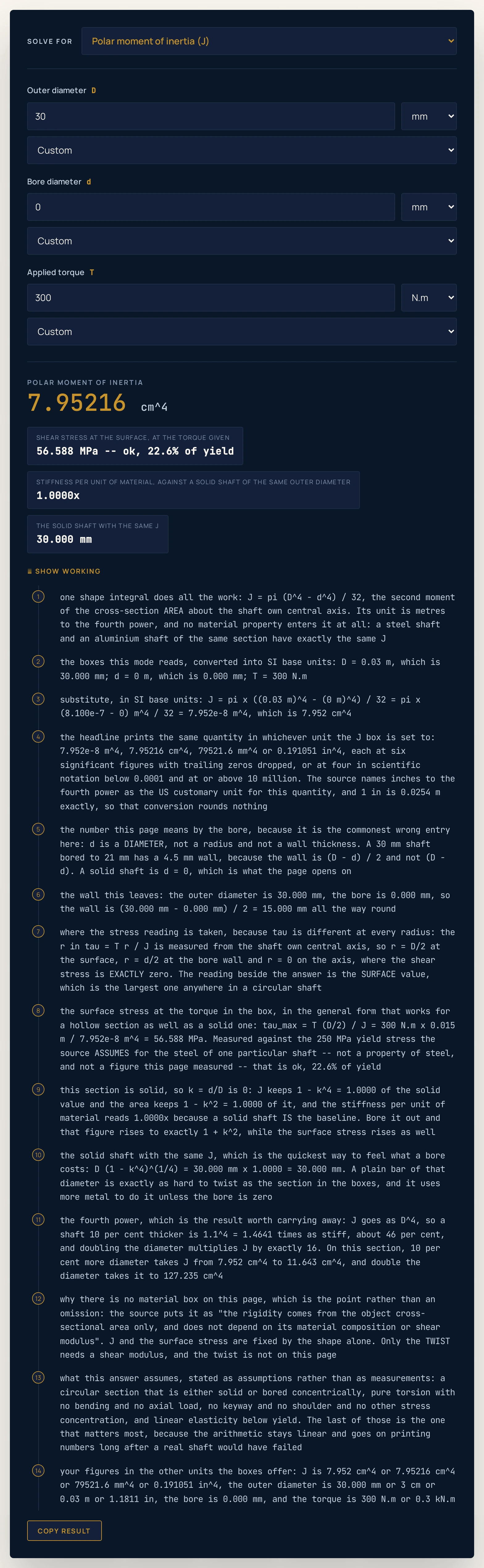
J is 7.95216 cm^4, the surface works at 56.588 MPa — ok, 22.6% of yield — and the equivalent solid shaft is the 30 mm shaft itself, because there is no hole in it yet. The torque in that box came from somewhere, and the torque calculator is where.Worked example: change one thing at a time
The table starts at the defaults, runs the unknown through all three modes on one state, bores the same shaft out twice, loads the real shafts, shows the fourth power as an exact doubling, walks every unit menu, and finally reaches the entries the calculator declines. Every answer and reading cell was taken from the running widget rather than worked out by hand. Where a cell and the tool ever part company, believe the tool.
| Step | Solving for | What you type | Headline answer | Shear stress at the surface | Stiffness per unit of material | Equivalent solid shaft |
|---|---|---|---|---|---|---|
| The page as it opens: a solid 30 mm shaft | Polar moment of inertia | D = 30 mm, d = 0 mm, T = 300 N.m | 7.95216 cm^4 | 56.588 MPa -- ok, 22.6% of yield | 1.0000x | 30.000 mm |
| The same state, solved for the diameter | Outer diameter | J = 7.9521564044 cm^4, d = 0 mm, T = 300 N.m | 30 mm | 56.588 MPa -- ok, 22.6% of yield | 1.0000x | 30.000 mm |
| The same state, solved for the bore | Bore diameter | J = 7.9521564044 cm^4, D = 30 mm, T = 300 N.m | 0 mm | 56.588 MPa -- ok, 22.6% of yield | 1.0000x | 30.000 mm |
| The same shaft bored to 70 per cent | Polar moment of inertia | D = 30 mm, d = 21 mm, T = 300 N.m | 6.04284 cm^4 | 74.468 MPa -- ok, 29.8% of yield | 1.4900x | 28.010 mm |
| The same shaft bored to 90 per cent | Polar moment of inertia | D = 30 mm, d = 27 mm, T = 300 N.m | 2.73475 cm^4 | 164.549 MPa -- ok, 65.8% of yield | 1.8100x | 22.974 mm |
| What bore leaves the 70 per cent J | Bore diameter | J = 6.04284 cm^4, D = 30 mm, T = 300 N.m | 21 mm | 74.468 MPa -- ok, 29.8% of yield | 1.4900x | 28.010 mm |
| A 17 mm bicycle spindle at the same torque | Polar moment of inertia | D = 17 mm, d = 0 mm, T = 300 N.m | 0.819966 cm^4 | 310.989 MPa -- OVER by 1.24x -- would have failed | 1.0000x | 17.000 mm |
| A 6 mm instrument shank at the same torque | Polar moment of inertia | D = 6 mm, d = 0 mm, T = 300 N.m | 0.0127235 cm^4 | 7.074 GPa -- OVER by 28.29x -- would have failed | 1.0000x | 6.000 mm |
| A 400 mm turbine shaft at 1000 MW and 50 Hz | Polar moment of inertia | D = 400 mm, d = 0 mm, T = 3183098.862 N.m | 251327 cm^4 | 253.303 MPa -- OVER by 1.01x -- would have failed | 1.0000x | 400.000 mm |
| Double the diameter, sixteen times the J | Polar moment of inertia | D = 50 mm, d = 0 mm, T = 300 N.m | 61.3592 cm^4 | 12.223 MPa -- ok, 4.9% of yield | 1.0000x | 50.000 mm |
| Half of it: the 25 mm shaft the 50 mm one doubles | Polar moment of inertia | D = 25 mm, d = 0 mm, T = 300 N.m | 3.83495 cm^4 | 97.785 MPa -- ok, 39.1% of yield | 1.0000x | 25.000 mm |
| The 25 mm shaft bored to 80 per cent | Polar moment of inertia | D = 25 mm, d = 20 mm, T = 300 N.m | 2.26416 cm^4 | 165.625 MPa -- ok, 66.2% of yield | 1.6400x | 21.914 mm |
| Ten per cent more diameter on the 30 mm shaft | Polar moment of inertia | D = 33 mm, d = 0 mm, T = 300 N.m | 11.6428 cm^4 | 42.516 MPa -- ok, 17.0% of yield | 1.0000x | 33.000 mm |
| The torque taken off altogether | Polar moment of inertia | D = 30 mm, d = 0 mm, T = 0 N.m | 7.95216 cm^4 | suppressed at zero torque | 1.0000x | 30.000 mm |
| The diameter typed in inches | Polar moment of inertia | D = 1.1811023622 in, d = 0 mm, T = 300 N.m | 7.95216 cm^4 | 56.588 MPa -- ok, 22.6% of yield | 1.0000x | 30.000 mm |
| The same J typed in mm to the fourth | Outer diameter | J = 79521.564044 mm^4, d = 0 mm, T = 300 N.m | 30 mm | 56.588 MPa -- ok, 22.6% of yield | 1.0000x | 30.000 mm |
| The same J typed in inches to the fourth | Outer diameter | J = 0.19105132182 in^4, d = 0 mm, T = 300 N.m | 30 mm | 56.588 MPa -- ok, 22.6% of yield | 1.0000x | 30.000 mm |
| The torque typed in kilonewton metres | Polar moment of inertia | D = 30 mm, d = 0 mm, T = 0.3 kN.m | 7.95216 cm^4 | 56.588 MPa -- ok, 22.6% of yield | 1.0000x | 30.000 mm |
| A bore equal to the outer diameter is declined | Polar moment of inertia | D = 30 mm, d = 30 mm, T = 300 N.m | no answer | - | - | - |
| A bore larger than the shaft is declined | Polar moment of inertia | D = 30 mm, d = 40 mm, T = 300 N.m | no answer | - | - | - |
| A negative bore is declined | Polar moment of inertia | D = 30 mm, d = -5 mm, T = 300 N.m | no answer | - | - | - |
| An outer diameter of zero is declined | Polar moment of inertia | D = 0 mm, d = 0 mm, T = 300 N.m | no answer | - | - | - |
| A shaft wider than 2 m is declined | Polar moment of inertia | D = 2500 mm, d = 0 mm, T = 300 N.m | no answer | - | - | - |
| A J above the solid J of that diameter is declined | Bore diameter | J = 7.96 cm^4, D = 30 mm, T = 300 N.m | no answer | - | - | - |
| An absurdly small J is declined | Outer diameter | J = 1e-20 cm^4, d = 0 mm, T = 300 N.m | no answer | - | - | - |
| A torque above 1e9 N.m is declined | Polar moment of inertia | D = 30 mm, d = 0 mm, T = 2e9 N.m | no answer | - | - | - |
Rows 1 to 3 are one state — a solid 30 mm shaft at 300 N·m — with the Solve for menu in each of its three positions. All three reading columns are identical down all three rows, because the readings describe the section rather than the mode. Row 3 is the one worth trying: the bore that gives a solid shaft its own J is 0 mm, not an error, and getting that answer rather than a failure is the whole reason this page computes the bore the way it does.
Rows 4 to 6 bore the same 30 mm shaft out and read the trade off the tool. At a 21 mm bore J falls from 7.95216 cm^4 to 6.04284 cm^4 — it keeps 0.7599 of the solid value — while the metal in the face falls to 0.5100 of it, so the stiffness per unit of material reads 1.4900x. At 27 mm those become 0.3439 and 0.1900, and the reading is 1.8100x. And the surface stress rises both times, from 56.588 MPa to 74.468 MPa to 164.549 MPa, because the same torque is carried on a smaller J. The gain is per unit of material, never per shaft.
Rows 7 to 9 are the honest rows. The same 300 N·m on a 17 mm spindle reads 310.989 MPa and on a 6 mm shank 7.074 GPa, which the verdict column marks OVER by 1.24x and OVER by 28.29x. The arithmetic is linear elastic and it never stops, so it goes on printing numbers for shafts that are no longer shafts. The 400 mm turbine row is the source’s own example, and the torque in it is what 1000 megawatts makes at 50 hertz — a step the power guide covers, since power is torque times angular speed.
Rows 10 and 11 are the fourth power with nothing hidden in it. The 50 mm shaft reads 61.3592 cm^4 and the 25 mm one 3.83495 cm^4: exactly 16 times, for every torque and every material, because doubling D multiplies D4 by 16. The surface stress goes the other way by exactly 8, from 97.785 MPa to 12.223 MPa. Row 13 is the cheaper version of the same lesson: 10 per cent more diameter is 1.14 = 1.4641 times the J, about 46 per cent more stiffness for 21 per cent more metal.
Rows 14 to 18 change nothing but the units and the torque. Taking the torque off suppresses the stress reading rather than printing 0 Pa beside a yield verdict, because an unloaded shaft still has a J. Typing the diameter as 1.1811023622 in, or the same J as 79521.564044 mm^4 or 0.19105132182 in^4, reproduces the figures they came from; the inch units are offered because the source names inches to the fourth power as the US customary unit, and 1 in is 0.0254 m exactly. If the torque you were handed is in pound-feet, the Nm to ft-lb converter puts it in the unit this box wants.
Rows 19 to 26 are the refusals, and they are refusals on the input rather than tidied-up output. A bore equal to the shaft gives exactly J = 0 and then an infinite stress; a larger bore gives a negative J; a J of 7.96 cm^4 is above the solid J of a 30 mm shaft, so no bore produces it. In every one of them the answer is words rather than an infinity or a NaN.
Formula and symbol reference
One relation does all the work: J = π(D^4 − d^4) / 32, for a circular section that is solid or bored concentrically, with d = 0 giving the solid πD^4 / 32. For a solid shaft of radius R the same quantity is πR^4 / 2, which is exactly twice the planar second moment of the same circle. Everything else on this page is that relation rearranged, or a quantity derived from the section it describes.
The stress that goes with it is tau = T · r / J at a distance r from the shaft’s own axis, so the surface value is T · (D/2) / J. The familiar 16T / (πD³) is that expression with the solid J already substituted in, which makes it wrong for a bored section; this page never uses it. Reading the relation backwards gives D = (32J / π + d^4) to the quarter power and d = (D^4 − 32J / π) to the quarter power. Where the T itself comes from — a force and a lever arm — is the torque guide.
There is deliberately no box for the material, and that is the result rather than a gap. The source states that the rigidity comes from the cross-sectional area only and does not depend on material composition or shear modulus, so J and the surface stress are identical in steel and in aluminium. A shear modulus is needed only for the twist angle, and it is a different modulus from the stretching one that the Young’s modulus calculator works in.
| Symbol | Meaning | SI unit | Values used on this page |
|---|---|---|---|
| J | Polar moment of inertia of the section: the second moment of the cross-section AREA about the shaft’s own axis, and the quantity that decides how hard it is to twist. Fixed by the shape alone, so it is identical for every material | metre to the fourth power | Boxes take cm^4, mm^4, m^4 or in^4: 7.9521564044 cm^4 is the default, the solid J of a 30 mm shaft. The box accepts 1e-14 to 1 m^4. |
| D | Outer diameter, all the way across the shaft. J goes as its FOURTH power, so this is the one number that really decides the answer | metre | Boxes take mm, cm, m or in: 30 mm is the default, which is 3 cm, 0.03 m or about 1.1811 in, with presets at 17, 30 and 400 mm. The box accepts 1e-4 to 2 m. |
| d | Bore diameter — the hole up the middle, measured as a DIAMETER. Not a radius and not a wall thickness: the wall is (D − d) / 2. Zero is a solid shaft | metre | Boxes take mm, cm, m or in: 0 is the default, with presets at 0, 21 and 27 mm, which are 0, 70 and 90 per cent of the 30 mm default. |
| T | Applied torque. It is an INPUT here and never the unknown: it sets the stress reading and has no effect on J at all | newton metre | Boxes take N.m, kN.m or N.mm: 300 N.m is the default, with presets at 25, 300 and 1500 N.m. The box accepts 0 to 1e9 N·m. |
| k | Bore ratio, d divided by D. The whole hollow-versus-solid argument is written in it: J keeps 1 − k4 and the area keeps 1 − k2 | dimensionless | A derived quantity: 0 on a solid shaft, 0.7000 on the 21 mm bore, 0.9000 on the 27 mm bore, 0.8000 on the 25 mm shaft bored to 20 mm. |
| r | Distance from the shaft’s own central axis, which is where the shear stress is measured from. D/2 at the surface, d/2 at the bore wall, 0 on the axis | metre | Not a box: the reading beside the answer is taken at r = D/2, the surface, which is the largest value anywhere in a circular shaft. |
| tau | Shear stress, spelled as a word here because CSS uppercases every label on the widget and that destroys a Greek letter. T r / J at radius r, so it is linear in r and exactly zero on the axis | pascal | A reading beside the answer: 56.588 MPa on the defaults, 74.468 MPa on the 70 per cent bore, 7.074 GPa on the 6 mm shank. |
| 1 + k2 | Stiffness per unit of material, against a solid shaft of the same outer diameter. Exactly (1 − k4) / (1 − k2), which is pure geometry with no material in it | dimensionless | A reading beside the answer: 1.0000x solid, 1.4900x at 70 per cent, 1.6400x at 80 per cent, 1.8100x at 90 per cent. |
The physics: why the fourth power decides everything
Twist a round shaft and each ring of metal resists in proportion to how far out it sits, twice over: once because it is being sheared further, and once because its lever arm about the axis is longer. That is why the quantity is an integral of r² over the area rather than the area itself. Integrate r² over a disc and the fourth power of the diameter falls out.
Every consequence worth knowing is in that exponent. Doubling the diameter multiplies J by exactly 16, so the twist falls by 16 and the surface stress by 8 — whatever the torque, whatever the length, whatever the metal. Ten per cent more diameter is 1.14, about 46 per cent more stiffness. Nothing on this page needs a material to say any of that.
The same exponent is why hollow wins. Boring a concentric hole of ratio k = d/D leaves J at exactly 1 − k4 of the solid value while the area falls to 1 − k², and the ratio of those two is exactly 1 + k². At k = 0.8 the section keeps 59.04 per cent of the stiffness on 36.00 per cent of the metal, a gain of 1.6400 — pure geometry, with no material in it anywhere.
The reason is the stress distribution, and it is worth seeing rather than taking on trust. tau = T · r / J is exactly linear in r, so it is exactly zero on the axis, exactly half the surface value at mid-radius, and exactly k times the surface value at the bore wall. The metal in the middle was barely carrying anything, which is why a driveshaft, a bicycle spindle and an aircraft control rod are tubes rather than bars — and why the bored shaft’s surface stress is nonetheless higher, because the same torque now runs through a smaller J.
One bridge is worth stating because it settles the name. The mass moment of inertia of a uniform shaft is exactly J times the density times the length, which is why one is in m4 and the other in kg·m2: the two differ by exactly a mass per unit of cross-sectional area. That is an identity, not a figure — no density is quoted anywhere in this cluster, so no kilogram metre squared number is either.
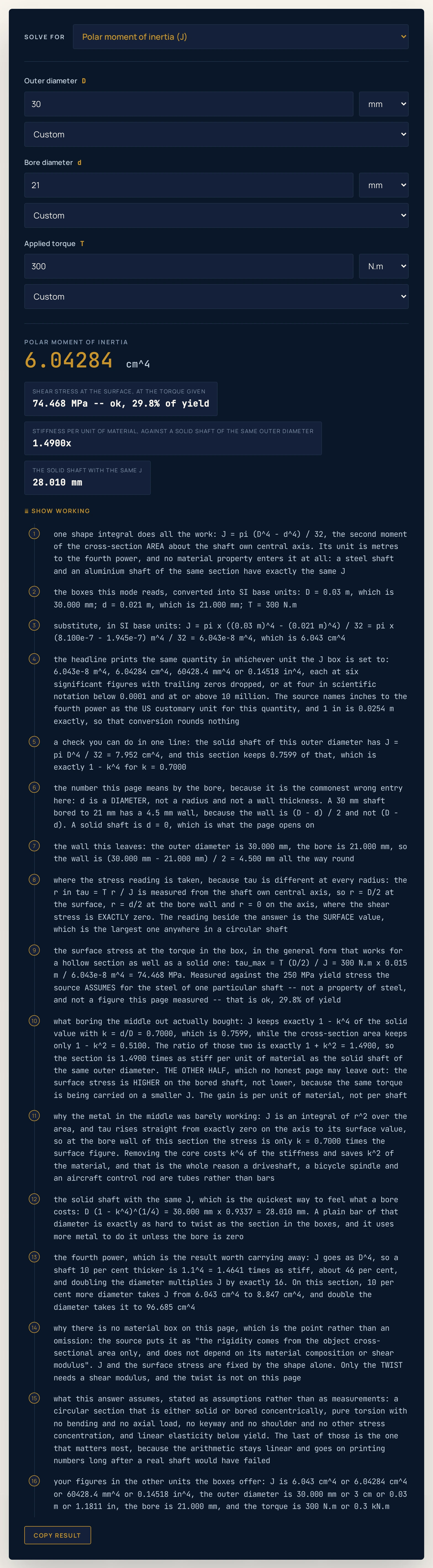
J keeps 0.7599 of the solid value and the metal only 0.5100, so the stiffness per unit of material reads 1.4900x — and the surface stress has gone up, to 74.468 MPa. The equivalent solid shaft is 28.010 mm: a 2 mm-thinner bar would be just as stiff, and would use more metal doing it.Where this arithmetic breaks down
The arithmetic here is exact to the last digit a double can hold. What goes wrong is physical, and one item on this list matters more than all the others.
- The arithmetic is linear elastic and it never stops
- This is the one to read. Stress is proportional to torque for ever in this model, so the page keeps printing numbers long after a real shaft would have broken. A 6 mm shank at 300 N·m prints
7.074 GPa, which is 28.29 times the only yield figure this cluster has a source for. The reading beside the answer says so in words; the headlineJnever will, becauseJis a property of the shape and cares nothing about whether the shaft survived. - The 250 MPa is one shaft’s assumed yield, not steel’s
- It is the figure the source states for the steel of its own example shaft, inside its own sample calculation, and it is quoted here as a reference to measure against rather than as a specification for anything. A real part has its own material certificate, its own heat treatment and its own factor of safety. Nothing on this page is a design allowable.
- Circular sections only — and the source says why
- The polar second moment of area can be insufficient for use to analyze beams and shafts with non-circular cross-sections, due their tendency to warp when twisted, and a torsion constant is substituted instead. That is the source’s own sentence, including its own grammatical slip, and it is the whole of what this page says about square, splined or keyed sections. No figure for any of them is published here.
- Pure torsion, with no features
- No bending, no axial load, no keyway, no shoulder, no press fit and no step in the diameter. Those are exactly where a real shaft fails, and it fails at the feature rather than in the plain section. This page will not quantify that, because nothing it is built on sources a stress concentration factor.
- The bore mode is the one ill-conditioned direction
- Going from
JandDto a bore takes a fourth root of the difference between two nearly equal numbers, and the fourth root magnifies. Near a solid shaft aJquoted to six significant figures pins the bore only to about 2.7 per cent of the diameter, which is 0.8 mm on a 30 mm shaft. That is why theJbox opens on eleven figures, why aJeven a whisker above the solid value is declined outright, and why the safe route is to solve forJfirst and then switch. - A concentric bore, and nothing else
- The hole is assumed to be on the axis. An eccentric bore, a cross-drilled hole or a hollow section with a seam is a different calculation that this page does not do, and offering a figure for one would be inventing it.
- This
tauis not viscosity’stau - The symbol is shared and the quantity is not: here it is the elastic shear stress in a twisted solid, set by a geometry, and in a fluid it is set by a velocity gradient and a viscosity. The viscosity guide is where that other one lives, and nothing on this page applies to it.
- A clean answer can be a coincidence of the numbers
- The 25 mm and 50 mm rows differ by exactly 16, and the 80 per cent bore reads exactly
1.6400x. Those are exact because the ratios are exact powers, not because the arithmetic is tidy — change the diameter to 33 mm and every figure turns ragged while every identity still holds to the last digit. - The calculator measures nothing — you supply the numbers
- Two diameters and a torque go in, one relation is used, and the answer describes the section you described. The case names on the buttons are shorthand for the four figures behind them and are not claims about any particular shaft, spindle or machine.
Where the polar moment is actually used
- Deciding whether to bore a shaft out
- Load the same shaft, 70 per cent bored and the trade is on screen in one line:
6.04284 cm^4against7.95216 cm^4, a reading of1.4900xper unit of material, and a surface stress up from56.588 MPato74.468 MPa. That is the whole decision — stiffness per gram against stress at the skin. - Sizing a shaft from the stiffness you need
- Point Solve for at the outer diameter and the question becomes the one a design actually asks. Because
Jgoes as the fourth power, doubling the stiffness needs only about 19 per cent more diameter, and sixteen times the stiffness is exactly twice. The working prints that factor for your own figures. - Finding how much of the middle you can take out
- Point Solve for at the bore, give the
Jyou must keep and the diameter you have, and the answer is the largest hole that still leaves it. Ask for theJof a 21 mm bore on a 30 mm shaft and you get21 mmback; ask for the solidJand you get0 mm, which is the honest answer rather than a failure. - Checking a stress against a yield figure
- The reading beside the answer turns a
Jinto something you can argue about.310.989 MPaon the 17 mm spindle comes withOVER by 1.24xattached, which is a far more useful sentence than the stress on its own. The yield it is measured against is the source’s assumption about one shaft, so treat the percentage as a comparison and not a verdict on your part. - Reproducing a published sizing calculation
- Load a 1000 MW turbine shaft: 400 mm solid at the torque 1000 megawatts makes at 50 hertz, which the source rounds its own radius to. The page prints
253.303 MPafor it — above the 250 MPa it was sized against, because stress goes as one over the radius cubed and the published radius was rounded down. That is why the source then applies a factor of safety. - Telling the two quantities apart
- If what you actually need is how hard a wheel, a disc or a rotor is to spin up, that is the mass moment of inertia in kg·m², it needs a mass, and the moment of inertia calculator is the page for it. This one needs no mass at all. The two differ by exactly a mass per unit of cross-sectional area, which is also why their units differ.
- Working in inches to the fourth power
- Section tables in US customary units quote this quantity in in4, which the source names as the customary unit for it. The
Jmenu offers it, and because 1 in is 0.0254 m exactly nothing is rounded on the way across. A 30 mm solid shaft is0.19105132182 in^4.
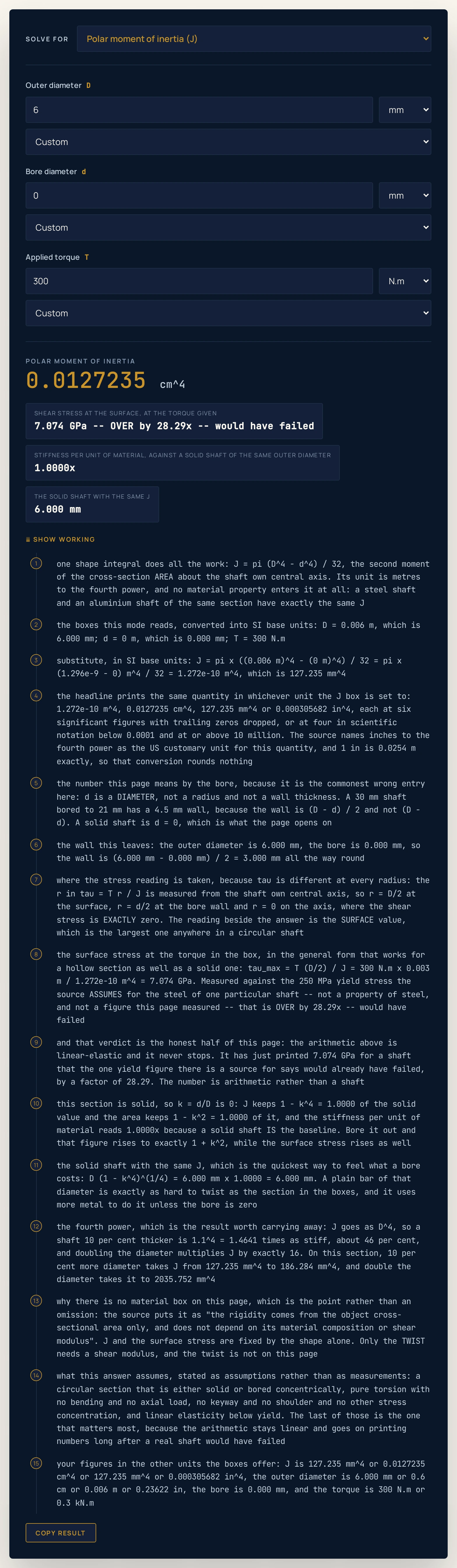
J is 0.0127235 cm^4 and the surface stress reads 7.074 GPa, flagged OVER by 28.29x -- would have failed. The arithmetic is perfectly happy; the shaft would not be. Every figure in the mechanics formula sheet behaves the same way once you leave the range it was meant for.Where to go next
For the argument this arithmetic supports — the fourth power, what hollow really buys, and why this quantity is not the one it is named after — read the polar moment of inertia guide, which this tool is the calculating half of. The moment of inertia guide is the other quantity: I in kg·m², for nine common shapes, about how hard a body is to spin up.
Four more posts pick up the pieces this page uses but does not explain. The torque guide is where the T comes from, the power guide is how a megawatt rating becomes a torque, the physics symbols guide is where the clash between this J and the other I is catalogued, and the mechanics formula sheet is the one-page reference.
Four tools sit next to this one. The moment of inertia calculator is the mass quantity, the torque calculator gives the torque from a force and a lever arm, the Young’s modulus calculator is the stretching modulus rather than the twisting one, and the Nm to ft-lb converter changes the torque unit. The moment of inertia simulator is the interactive version of the quantity this one is confused with.
The full physics lab library and the calculator index are open too.
Frequently asked questions
What does the polar moment of inertia calculator work out?
It solves J = pi times D to the fourth minus d to the fourth, all over 32, for any one of three quantities: the polar moment of inertia of a round shaft, its outer diameter, or the bore diameter up the middle. Beside the answer it prints the shear stress at the surface at the torque you gave, how much stiffer per unit of metal the section is than a solid shaft of the same outer diameter, and the diameter of the solid bar that would be equally hard to twist.
Is this the same as the moment of inertia?
No, and the two are only named alike. This one is an integral over the cross-section area, its unit is metres to the fourth power, it needs no mass at all, and it says how hard a shaft is to twist. The moment of inertia that appears in rotation problems is a mass quantity in kilogram metres squared, it needs a mass and a radius, and it says how hard a body is to spin up. The two differ by exactly a mass per unit of cross-sectional area.
Is the bore a diameter or a radius?
A diameter, and it is not a wall thickness either. A 30 mm shaft with a 21 mm bore has a wall of 4.5 mm, because the wall is half the difference between the two diameters. Entering a radius there is the commonest reason an answer on this page comes out wrong, and entering a wall thickness is the second commonest.
Why is there no box for the material?
Because the quantity does not have one. The source puts it plainly: the rigidity comes from the cross-sectional area only and does not depend on the material composition or the shear modulus. A steel shaft and an aluminium shaft of the same section have exactly the same J and exactly the same surface stress at the same torque. Only the twist angle needs a shear modulus, and the twist is not on this page.
Why does a hollow shaft come out stiffer for the metal in it?
Because J is an integral of the radius squared over the area, so the metal near the axis contributes almost nothing. Boring the middle out costs k to the fourth of the stiffness and saves k squared of the material, and the ratio of those is exactly one plus k squared. The honest other half is that the surface stress goes up, not down, because the same torque is carried on a smaller J.
Why does the calculator refuse some entries?
Because the number it would return would be arithmetic rather than physics. A bore at or past the outer diameter is refused outright, because equal diameters give exactly zero J and then an infinite stress, and a bigger bore gives a negative J. Each box is also checked against its declared range rather than merely against zero, since asking for the diameter that gives a J of 1e-300 returns a perfectly finite answer below 1e-70 metres.
Why does the bore mode sometimes say there is no solution?
Because the largest J a shaft of a given diameter can have is the solid value, pi D to the fourth over 32. Any J above that has no bore at all, so the page declines rather than inventing one. Near that ceiling the mode is also the one ill-conditioned direction on the page: the fourth root magnifies, so a J quoted to six figures only pins the bore to roughly three per cent of the diameter.
What does the stress reading mean when it says the shaft would have failed?
It means the arithmetic has gone on past the point where it describes a shaft. Everything here is linear elastic, so the stress rises in proportion to the torque for ever, and a 6 mm shank at 300 N.m prints 7.074 GPa. That is over 28 times the 250 MPa yield the source assumes for the steel of its own example shaft, which is a reference and not a specification.
Does this work for a square or splined shaft?
No. The source is explicit that the polar second moment of area can be insufficient for use to analyze beams and shafts with non-circular cross-sections, due their tendency to warp when twisted, and that a torsion constant should be substituted instead. This page is for a circular section, solid or concentrically bored, and no figure for any non-circular section is published here.
Why is the J box filled with eleven significant figures?
Because the bore mode takes a fourth root of the difference between two nearly equal numbers. Rounding J even slightly turns a solid shaft into a thin imaginary bore, so the opening value is the exact solid J of a 30 mm shaft rather than the six-figure version the headline prints. You can type far fewer digits in every other mode without noticing a thing.
References & formula source
- The relation solved on this page is the second moment of a circular cross-section area about the axis of the shaft, J as the integral of r squared over the area. For an annulus of outer diameter D and bore diameter d that integral is pi times D to the fourth minus d to the fourth, all divided by 32, and setting d to zero gives the solid case pi D to the fourth over 32. The same quantity is pi R to the fourth over 2 for a solid shaft of radius R, which is twice the planar second moment of the same circle by the perpendicular axis theorem. It is stated here rather than derived.
- The shear stress is T r over J at a distance r from the shaft’s own central axis, so it is exactly zero on the axis, exactly half the surface value at mid-radius, and largest at the surface of a circular shaft. The surface form used in every mode here is T times D over 2, divided by J. The familiar 16 T over pi D cubed is the same expression with the solid J substituted in, and it is wrong for a bored section; this page never uses it.
- The source for the relation, the unit and the limitation is the Wikipedia article on the second polar moment of area, read on 9 November 2026. Two things are quoted from it rather than paraphrased: that the rigidity comes from the cross-sectional area only and does not depend on material composition or shear modulus, and that the quantity can be insufficient for use to analyze beams and shafts with non-circular cross-sections, due their tendency to warp when twisted. The 250 MPa the stress reading is measured against is that article’s own stated assumption about the steel of one example shaft, inside its own sample calculation. It is a reference figure, not a specification, and no page in this cluster calls it a property of steel.
- An independent reference script, written before this page existed and sharing no code with it, runs 2260 checks with 0 failures. It pins every figure quoted on this page, round-trips the outer diameter from J over the whole diameter ladder and the bore from J and D over all 64 diameter-and-bore pairs to one part in a million million, and asserts the three exact identities the page leans on: that J keeps exactly 1 minus k to the fourth of the solid value, that the area keeps exactly 1 minus k squared, and that the ratio of those is exactly 1 plus k squared.
- That same script pins the three guard traps this page is built around as bare arithmetic, so the reason the guards are shaped the way they are survives in the log even if the solvers change. Checking only that a figure is positive lets an infinite one through, because infinity is greater than zero; checking only that the answer came out finite misses the cases that quietly return zero; and the obvious one-line inverse for the bore returns NaN for a plain solid shaft, because the bracket it takes a fourth root of is mathematically zero and lands a few units in the last place negative. Every box here is therefore checked against the range printed under the widget, and the bore mode refuses on the input rather than on the output.
- What this page assumes, stated as assumptions: a circular section, either solid or bored concentrically; pure torsion, with no bending, no axial load, no keyway, no shoulder and no other stress concentration; and linear elasticity below yield. The last of those is the one that matters, because failure is nowhere in the relation: the stress scales on with the torque, and a finite answer still comes back for metal that has already gone. Nothing here is a measurement of any particular component, and the case names on the buttons are shorthand for the four figures behind them.
- Every figure quoted in the prose and the tables above is either a string this calculator printed for the inputs named beside it, or a constant the cluster physics contract fixes, or a ratio the unit tests assert. Where a cell and the running widget ever part company, believe the widget. Anything this page declines to put a number on is declined because the model cannot produce one, not because the figure was omitted for brevity.
- Further reading: Second polar moment of area — Wikipedia