The right-hand rule simulator is a free interactive trainer for the one thing a formula will not tell you on its own: which way. Three buttons choose the rule — Moving charge for F = q v x B, Straight wire for B = µ0 I / 2πr, Coil for B = µ0 n I — and the controls under them are words rather than arrows: right, left, up, down, out of page, into page. Pick any two of those and the lab draws the third and names it, as down (-y) or out of the page (+z). Six directions is the whole range, and that restriction is what lets the answer be a phrase instead of three numbers.
Right-Hand Rule Trainer
You know two directions and you need the third. One convention everywhere on this page: +x is right across the screen, +y is up it, +z is out of the page toward you, so into the page is −z. A circle with a dot means out of the page; a circle with a cross means into the page. All three rules use conventional current, which runs opposite to the electron drift. Arrow lengths on the canvas are indicative, not to scale, and the trainer covers only the six axis directions.
Load a real case onto the trainer
Each button presses the rule, the direction, the sign or the sense it needs and then writes the sliders, so a load never inherits half of the case before it. The status line underneath quotes the panel straight back, and it quotes all three rules at once because the lab works all three out on every change — only one of them is on screen. Two of the six are deliberately settings with no force at all, which is where the direction card stops naming an axis and the strip names a cause instead.
Pick a case above, or press the direction pads and drag the sliders yourself.
What Is the Right-Hand Rule Simulator?
The right-hand rule simulator is a free interactive physics lab that runs in your browser, with nothing to install and no sign-up. It is a direction trainer rather than a magnitude explorer: you pick two directions from a pad of six words — right, left, up, down, out of page, into page — and the lab draws the third and names it in words. Three buttons across the top of the panel switch between the three rules the one hand serves, Moving charge, Straight wire and Coil, and only one rule’s controls are on screen at a time.
One axis convention holds everywhere on the page and is stated before any direction word is used: +x is right across the screen, +y is up it, and +z comes out of the page towards you. A circle with a dot on the drawing is out of the page and a circle with a cross is into it. All three rules use conventional current, which runs opposite to the electron drift. Assume the other sense for z and every answer the lab gives comes out reversed.
Each rule answers with three cards and a two-cell check grid. At the setting the lab boots in — velocity right, field out of page, a positive charge of 1 e at 3.0e6 m/s in 0.40 T — Force direction reads down (-y), Force magnitude 1.923e-13 N and Angle from v to B 90 deg, beside Charge q +1 e. Press negative (-) and the direction card alone flips to up (+y).
Switch to Straight wire and a current running right gives out of the page (+z) at 40.00 µT above the wire, with 20.00 µT on the card for twice that distance. Switch to Coil and an anticlockwise current seen from the right end puts the north pole at the right end (+x) with 2.5133 mT inside.
The lab is honest about the two ways a direction question has no answer. Turn the field along the velocity and Force direction stops naming an axis: it reads no direction (the force is zero) and the strip under the drawing names which of the causes applied, v is parallel to B or v is antiparallel to B. The force is always computed from the cross product and never from the sine form, so the antiparallel case reads 0 N on the force card while the q v B sin(angle) check card beside it reads 2.355e-29 N — floating-point dust the cross product does not produce.
Two limits are deliberate. The trainer covers only the six axis directions, which is exactly what lets it answer in a phrase rather than a number; a velocity and a field that lie between the axes belong to the right-hand rule calculator. And arrow lengths on the drawing are indicative rather than to scale, which the canvas caption states on itself.
| Control | What it sets | Range, step or default |
|---|---|---|
| Which rule | three rule buttons | Moving charge, Straight wire or Coil; boots on Moving charge |
| Direction pads | six direction words | right, left, up, down, out of page, into page — one pad each for the velocity, the field and the current |
| Charge sign | positive or negative | two buttons, boots positive; the force card flips and nothing else does |
| Charge size | 1 to 5 e | steps of 1 e, boots at 1 e |
| Speed v | 0.5 to 10.0 million m/s | steps of 0.1 million m/s, boots at 3.0 million m/s |
| Field B | 0.05 to 1.00 T | steps of 0.05 T, boots at 0.40 T |
| Where you stand | four slots beside the wire | relabelled from the current direction; the slot is kept when the current moves, not the word |
| Wire current I | 0.5 to 50.0 A | steps of 0.5 A, boots at 10.0 A |
| Distance r | 0.005 to 0.500 m | steps of 0.005 m, boots at 0.050 m |
| Current sense | anticlockwise or clockwise | two buttons, both read from the right end; boots anticlockwise |
| Coil current I | 0.1 to 5.0 A | steps of 0.1 A, boots at 2.0 A |
| Turns per metre n | 100 to 5000 per metre | steps of 100 per metre, boots at 1000 per metre |
How to use the right hand rule physics simulator
- Read the band above the drawing before you touch a control. It fixes the convention the whole lab depends on:
+x is right across the screen, +y is up it, +z is out of the page toward you. A circle with a dot on the canvas is out of the page and a circle with a cross is into it, and all three rules use conventional current. Assume the other sense forzand every answer reverses. - Now read the three cards as the lab boots. Force direction reads
down (-y), Force magnitude1.923e-13 Nand Angle from v to B90 deg, with Charge q at+1 ebeside them. The strip under the drawing spells the same thing out as a cross product:v x B: right x out of page = down. - Press
negative (-)and change nothing else. One card moves. Force direction turns toup (+y), Charge q reads-1 e, and Force magnitude holds at1.923e-13 N— the sign of the charge reverses the force without resizing it. - Walk the Field B pad round and watch the force follow. With the velocity left at
right,upgivesout of the page (+z)andinto pagegivesup (+y), both still at1.923e-13 N. Those two are worth doing one after the other, because they are the pair most often got backwards on a diagram. - Press
lefton the same pad for the case that has no answer. Force direction stops naming an axis and readsno direction (the force is zero), Force magnitude reads0 N, the angle reads180 deg, and the strip saysv x B: right x left = zero; v is antiparallel to B. The check card beside it reads2.355e-29 N, and the fixed line at the foot of the panel says which of the two is the force. - Drag Speed v and Field B and watch what cannot move. The speed runs from 0.5 to 10.0 million metres per second in steps of 0.1 million, printed as
3.0e6 m/sat the boot value; the field runs 0.05 to 1.00 T in steps of 0.05, printed as0.40 T. Both move the magnitude and neither touches the direction card, because the direction came from the pads. - Press
Straight wire. The moving-charge controls go and the grip rule arrives: Current I runs with the same six words, and From the wire, you go with four. At the boot values — currentright, youup,10.0 Aand0.050 m— the cards readout of the page (+z),40.00 µTand0.050 m, and the strip readsI x r: right x up = out of page. - Press
downon the stand pad and nothing but the direction changes. The field card turns tointo the page (-z)while40.00 µTholds, which is the whole of the grip rule in one press: cross the wire and you cross the field with it. - Drag Distance r from
0.050 mto0.100 m. The field card halves to20.00 µTand the B at twice that distance cell beside it halves again to10.00 µT. That second cell is there so the inverse-distance law can be read off without moving the slider at all, which is the one piece of arithmetic on this rule you never have to leave the panel for. - Press
out of pagefor the current and look at the stand pad. Its four buttons relabel themselves toright·left·up·down, because those are now the four directions perpendicular to the wire. The lab keeps your slot rather than your word: the first slot wasupwith the current along x and isrightwith the current along z. - Press
Coiland read which end is north. Withanticlockwise (from the right end),2.0 Aand1000 /m, North end readsright end (+x), Field inside2.5133 mT, and the South end cellleft end (-x). Pressclockwise (from the right end)and the two ends swap while the field inside does not change at all. - Drag Turns per metre n to
2000 /m. Field inside doubles to5.0265 mTand the north end stays where it was, because turns density sets how strong the field is and the sense of the current sets which way it points. That is the one relation of the three with a calculator of its own: the solenoid magnetic field calculator solvesB = µ0 n Ifor any one of its three quantities, so you can also ask it what turns per metre or what current a field you need would take. - Read the caption on the drawing last, and read it as a claim. At the boot setting it says
F = q v x B: v right, B out of page, positive charge: F is down, thenF magnitude 1.923e-13 N at 90 deg between v and B, then the warning thatarrow lengths are indicative, not to scale. The red arrow really is drawn downward, and the caption is checked against the drawing instructions rather than against a flag. - Press
Reset to the default casewhen you have lost track. It restores the rule, all three direction pads, the sign, the stand slot, the coil sense and all seven sliders at once. It is the only control that reaches into more than one rule.
The step worth repeating is the third one. Load Proton, field out of the page, then press negative (-) with your eye on the magnitude card. One number out of five changes its sign and nothing changes its size. That is the single most-missed point in the topic, and it takes one button to settle.
For what the rule is — the three forms as physics, the full 36-pair direction table, the four mistakes that account for most wrong answers, and eight worked problems — read the full guide to the right-hand rule. This page is about the panel and the drawing: which card answers which question, and where the picture gives a line up before the numbers do.
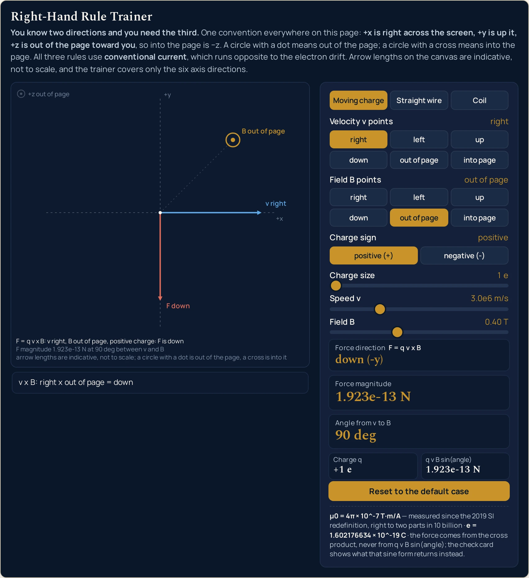
right, field out of page, a positive charge of 1 e at 3.0e6 m/s in 0.40 T. Force direction reads down (-y) at 1.923e-13 N and 90 deg. Only one of the three vectors is an arrow in the plane of the screen; the field is the circled dot, because it is pointing at you.Worked example: turn one thing around at a time
Every row below is one setting of the pads and the sliders, and every cell is a string the running lab printed there. The seven moving-charge settings come first; the last column is the check card, which exists so that one row of the table can disagree with itself in public. Where a cell and the lab ever part company, believe the lab.
| Setting | Force direction | Force magnitude | Angle shown | Sine check card |
|---|---|---|---|---|
| velocity right, field out of page, positive | down (-y) | 1.923e-13 N | 90 deg | 1.923e-13 N |
| the same, charge sign negative | up (+y) | 1.923e-13 N | 90 deg | 1.923e-13 N |
| velocity right, field up | out of the page (+z) | 1.923e-13 N | 90 deg | 1.923e-13 N |
| velocity right, field into page | up (+y) | 1.923e-13 N | 90 deg | 1.923e-13 N |
| velocity right, field right | no direction (the force is zero) | 0 N | 0 deg | 0 N |
| velocity right, field left | no direction (the force is zero) | 0 N | 180 deg | 2.355e-29 N |
| velocity up, field right, speed 2.0e6 m/s | into the page (-z) | 1.282e-13 N | 90 deg | 1.282e-13 N |
Rows 1 and 2 are the whole argument of the page in two lines. The same velocity in the same field gives down (-y) for a positive charge and up (+y) for a negative one, at an identical 1.923e-13 N. Nothing about the hand changed between those rows; only the sign in front of the cross product did.
Rows 3 and 4 move the field instead of the charge. Turning the field up throws the force out of the plane of the page altogether, to out of the page (+z); turning it from out of page to into page flips the force from down (-y) to up (+y). Those two rows are why the axis convention is restated on the drawing itself.
Rows 5 and 6 are the pair to look at twice. Both read no direction (the force is zero) and both read 0 N, but their check cards read 0 N and 2.355e-29 N. The second of those is the double-precision sine of 180 degrees, 1.2246e-16, surviving into a product; the cross product returns an exact zero in the same instant. The force is the 0 N, and the strip names which cause applied rather than printing an axis for a vector that has none.
Row 7 is a direction, not a size. Turn the velocity up with the field right and the force goes into the page (-z), at 1.282e-13 N because the speed slider is at 2.0e6 m/s rather than its boot value. Read it against row 1: the same hand, two of the six directions swapped, and an answer that has left the page.
The grip rule, and the only card pair that halves
Switch to Straight wire and the question changes from where a charge is pushed to where the field goes. The first four rows below hold the current at 10.0 A and 0.050 m and move only the two direction choices; the fifth moves the distance instead.
| Setting | Field direction where you stand | Field magnitude | Distance from the wire | Field at twice that distance |
|---|---|---|---|---|
| current out of page, you stand right | up (+y) | 40.00 µT | 0.050 m | 20.00 µT |
| current right, you stand up | out of the page (+z) | 40.00 µT | 0.050 m | 20.00 µT |
| current right, you stand down | into the page (-z) | 40.00 µT | 0.050 m | 20.00 µT |
| current left, you stand up | into the page (-z) | 40.00 µT | 0.050 m | 20.00 µT |
| current right, you stand up, r = 0.100 m | out of the page (+z) | 20.00 µT | 0.100 m | 10.00 µT |
Read rows 2 and 3 against each other first. Standing above the wire gives out of the page (+z) and standing below it gives into the page (-z), at the same 40.00 µT, which is what circulation means: the field has no single direction, only a sense of going round. Row 4 reverses the current instead of your position and gets the same reversal, so two reversals together would put you back where you started.
Rows 2 and 5 are the inverse-distance law on one card pair: 40.00 µT at 0.050 m and 20.00 µT at 0.100 m, with the B at twice that distance cell printing the second figure while the slider is still on the first. This trainer stops at the field and never puts a charge into it; what a field of that size then does to one — Magnetic force from F = qvB, the Radius r of the circle it bends the charge onto and the Period T of that orbit — is what the magnetic field and Lorentz force lab runs as an animation.
The coil, and the one card the sense does not move
The third rule has only two directions to choose between, both read looking at the right-hand end of the coil, so its table is short. What it shows is which card the sense of the current controls and which card it does not.
| Setting | North end | South end | Field inside | Turns per metre |
|---|---|---|---|---|
| anticlockwise from the right end, 1000 turns per metre | right end (+x) | left end (-x) | 2.5133 mT | 1000 /m |
| clockwise from the right end, 1000 turns per metre | left end (-x) | right end (+x) | 2.5133 mT | 1000 /m |
| anticlockwise from the right end, 2000 turns per metre | right end (+x) | left end (-x) | 5.0265 mT | 2000 /m |
Rows 1 and 2 swap the two ends and leave 2.5133 mT exactly where it was. Rows 1 and 3 double the turns density and double the field to 5.0265 mT while the north end stays at the right end (+x). So the sense of the current owns the two end cards and the two sliders own the field card, and no setting of this rule lets either group reach into the other.
Formula and symbol reference
The panel prints each of its three relations inside the label of the card it feeds, so no answer arrives without the rule that produced it. F = q v x B sits above Force direction, B = µ0 I / 2πr above Field magnitude, and B = µ0 n I above Field inside. None of the three is derived here.
The hand is assigned differently in each of the three, which is the most common reason a reader who has the first rule right still gets the third one backwards. The table below names what the hand does in each case and which card holds the answer.
| Rule | What the hand does | What the lab answers with | The card that prints it |
|---|---|---|---|
| Moving charge | Fingers along the velocity, curl them towards the field, and the thumb gives the cross product. For a negative charge, reverse what the thumb gave. | one of the six direction phrases, or no direction (the force is zero) |
Force direction, labelled F = q v x B |
| Straight wire | Thumb along the conventional current and let the fingers curl round the wire: the curled fingers, not the thumb, are the answer here. | the phrase for the side you are standing on, such as out of the page (+z) |
Field direction where you stand, labelled B along I x r |
| Coil | Fingers curling the way the current runs round the turns, and the thumb then points out of the north end. | right end (+x) or left end (-x) |
North end, labelled curl the fingers with I |
| Symbol | Meaning | SI unit | In this lab |
|---|---|---|---|
| v | Velocity of the charge. Its direction comes from the six-button Velocity v points pad and its size from the Speed v slider, which are two separate controls on purpose | metre per second | 0.5 to 10.0 million in steps of 0.1 million, printed beside the slider: “3.0e6 m/s” at the boot value and “2.0e6 m/s” in the last row of the table above. |
| B | Magnetic field. Again a direction from a pad and a size from a slider, so you can turn the field right round without changing its strength | tesla | 0.05 to 1.00 in steps of 0.05: “0.40 T” at the boot value. Only the moving-charge rule has this slider; the other two rules compute their field rather than being given one. |
| q | Charge, with its sign. The Charge sign pair gives the sign and the Charge size slider the size in elementary charges | coulomb (the slider is in elementary charges) | 1 to 5 in steps of 1, with the signed value on its own cell: “+1 e” at the boot value, “-1 e” after one press of negative (-). |
| F | Magnetic force on that charge, on the headline card. The card label prints the relation that produced it, so the answer never arrives without the rule | newton | a three-decimal mantissa: “1.923e-13 N” at the boot setting, “1.282e-13 N” at 2.0e6 m/s, and the exact “0 N” whenever the velocity lies along the field. |
| angle from v to B | Angle between the two vectors you chose, on the third card. With six axis directions to choose from there are only three answers it can ever print | degree (the SI unit is the radian) | exactly “0 deg”, “90 deg” or “180 deg”, and nothing in between is reachable. |
| I | Current, on two separate sliders because the two rules that use it work over quite different ranges | ampere | the wire rule runs 0.5 to 50.0 in steps of 0.5 and prints “10.0 A” at its boot value; the coil rule runs 0.1 to 5.0 in steps of 0.1 and prints “2.0 A”. |
| r | Distance from the wire to the point where you are standing, in the wire rule only | metre | 0.005 to 0.500 in steps of 0.005: “0.050 m” at the boot value and “0.100 m”, ten notches further out, in the last row of the wire table above. |
| n | Turns per metre on the coil. It is a turns density, not a number of turns, which is why the relation needs no length | per metre | 100 to 5000 in steps of 100: “1000 /m” at the boot value, “2000 /m” for the doubling in the coil table. |
| the magnetic constant | Constant in both field relations, on the fixed line at the foot of the panel rather than on any card. It is not a control | tesla metre per ampere | a constant, printed as “µ0 = 4π × 10^-7 T·m/A”, with the lab’s own note that it has been a measured quantity since the 2019 SI revision and agrees with that figure to about two parts in ten billion. |
| e | Elementary charge, also on the fixed line. It is what the Charge size slider counts in | coulomb | a constant: “e = 1.602176634 × 10^-19 C”, exact by the 2019 definitions of the SI units. |
The row worth reading twice is the angle. Every other readout on the panel is continuous in the control that drives it; that one can only ever print three values, because six axis directions cannot be at any other angle to each other. A velocity and a field pointing anywhere else are the job of the right-hand rule calculator, which takes six components and gives a unit vector back.
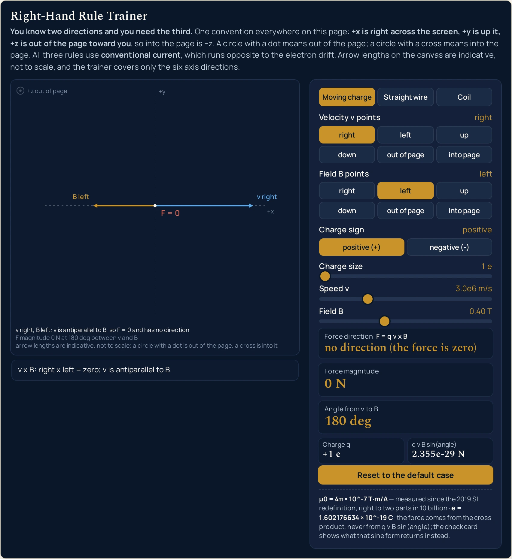
left, dead against the velocity: Force magnitude reads 0 N while the q v B sin(angle) cell beside it reads 2.355e-29 N. No red arrow is drawn — the letters F = 0 are printed at the origin instead, and the caption names the cause rather than an axis.The physics: what the picture can honestly claim
The caption is the part of this drawing to trust, because it is the part that is checked. Its first line states the answer in words, and the arrow and arc instructions the canvas actually received are compared against that line rather than against the variable the drawing branch had just set. If the caption says the force is down, the red arrow was drawn downward.
That is also why the drawing says in its own third line that arrow lengths are indicative rather than to scale. The three arrows of the moving-charge rule are given lengths that fit the box; the force is a hundred-thousandth of the velocity in SI units, so a scale picture of all three would show two of them and a dot. Compare sizes from the cards, and directions from the picture.
The straight-wire rule is drawn two quite different ways, and the difference is a matter of honesty rather than of style. With the current running out of or into the page the field loops lie flat in the page, so the lab draws three concentric circles with six arrowheads on them, going anticlockwise on screen for a current out of the page.
With the wire lying in the page those same loops stand perpendicular to it, and an arrowhead drawn on one would claim an in-plane direction the field simply has not got. So the lab draws rows of circled dots on one side of the wire and circled crosses on the other, each computed from the cross product at that point, leaves the faint perspective loops arrowhead-free, and adds a small inset labelled looking along the current — the one view in which the circulation really is a rotation in the plane of the screen.
What a magnetic field is, and why a charge moving across one travels on a circle at constant speed, belongs to the guide to the magnetic field rather than to this panel. The perpendicularity behind that is on the screen, though: the force card and the angle card together never once describe a force with a component along the velocity.
All three rules read the conventional current, which runs opposite to the drift of the electrons, and the band above the drawing says so before the grip rule or the coil rule is used. Getting that one substitution the wrong way round reverses every field direction on the canvas. The guide to electric current sets out why the convention is the way it is.
Changing a direction, a sign, a sense or the rule regrows the arrows over about a quarter of a second, which is the drawing telling you that the answer moved rather than merely its size. Dragging a size slider starts no animation: the numbers change and the geometry does not. The lab also boots at rest with its arrows at full length, so the first thing you see is a finished picture.
Narrow the window and the canvas gives things up in a fixed order rather than shrinking everything together. Each caption line has a ladder of shorter forms, and a line that will not fit in any of them is dropped from the bottom upwards, so the line naming the answer is the last to survive. The two insets need a wide canvas and are simply absent on a narrow one, which is honest: a picture too small to be read is worse than no picture.
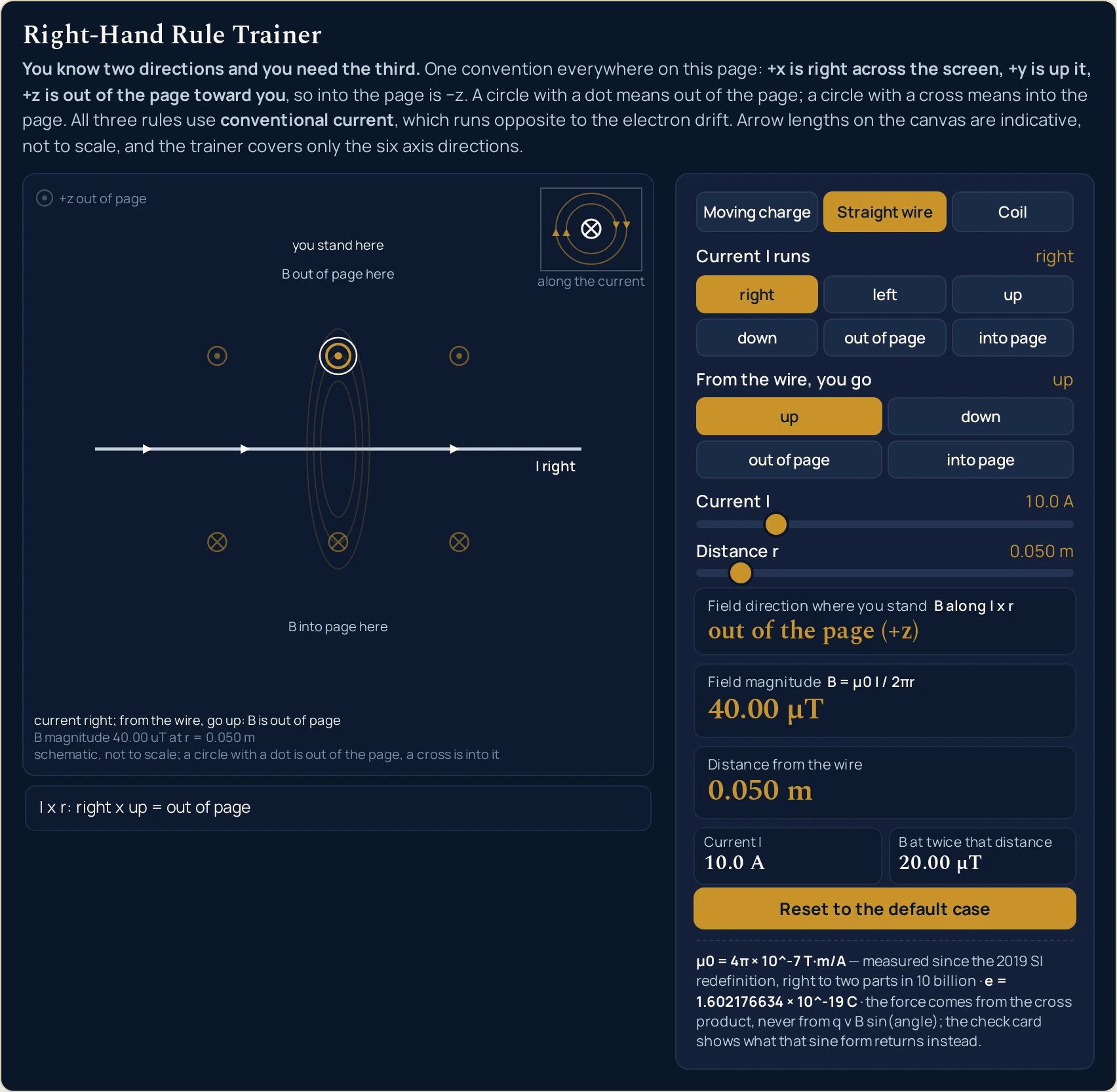
right at 10.0 A and you standing up from it, reading out of the page (+z) at 40.00 µT. Three circled dots above the wire, three circled crosses below, not one arrowhead on the three faint perspective loops, and the circulation shown honestly only in the end-on inset — whose label has already shortened to along the current at this width.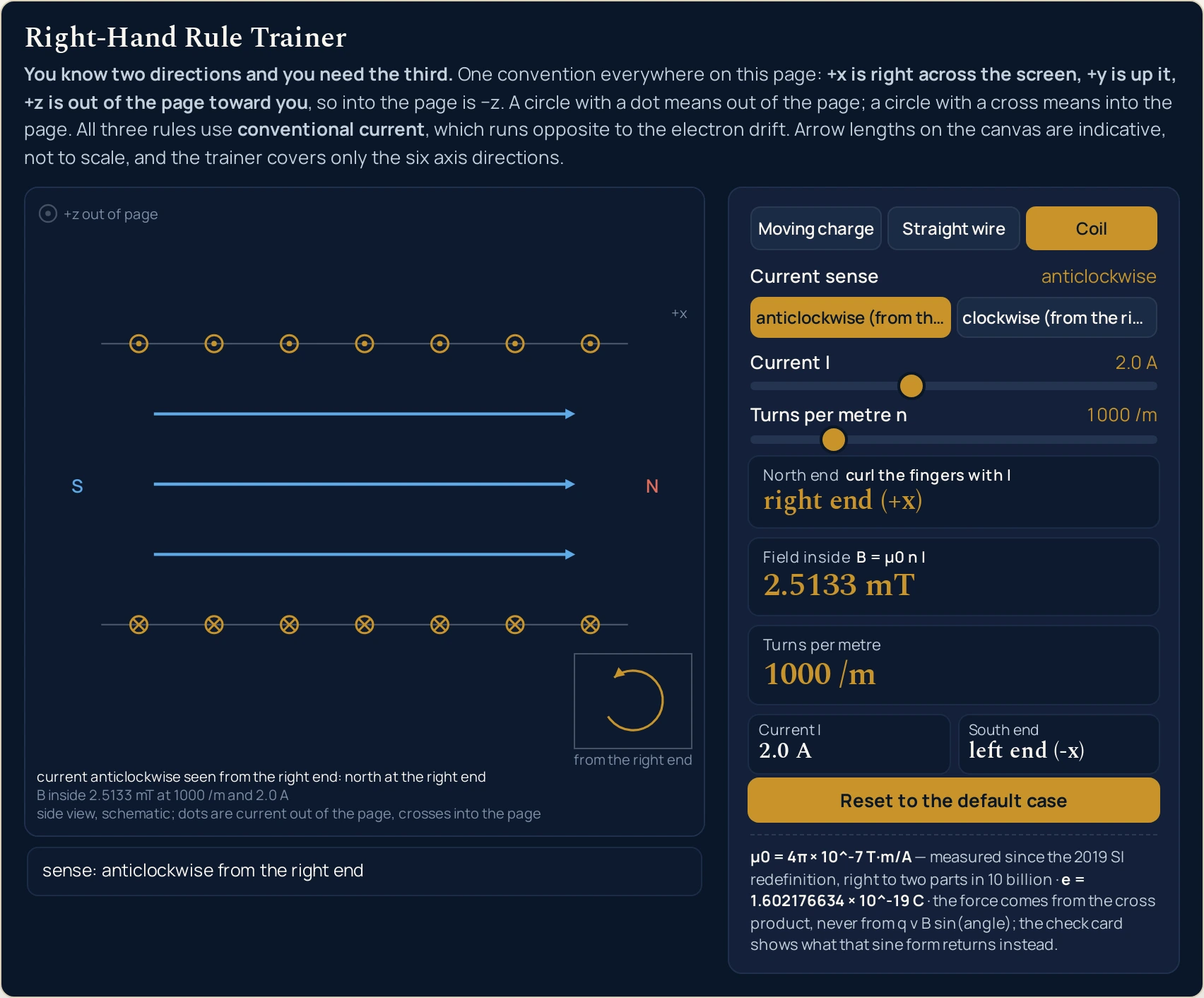
anticlockwise (from the right end), 2.0 A and 1000 /m: North end right end (+x), South end left end (-x), Field inside 2.5133 mT. The turns carry circled dots along the top and circled crosses along the bottom rather than arrowheads, and the three arrows through the bore run from the S end to the N one.Where the right-hand rule simulator breaks down
The lab solves its own model exactly, so nothing on the screen ever fails. Everything below is a limit of that model, of the six directions the pads offer, or of what a canvas a few hundred pixels wide can carry, and each item says what the lab does about it.
- Six directions, and nothing between them
- The pads offer
right,left,up,down,out of pageandinto page, and that is the entire input space: 36 ordered pairs for the moving-charge rule, of which 12 give no force at all. The restriction is deliberate, because it is what lets an answer be a phrase rather than three numbers. It also means the Angle from v to B card can only ever print0 deg,90 degor180 deg, and no setting of the pads reaches anything else. - The arrows are not to scale, and the drawing says so
- Arrow lengths on the canvas are indicative. The third caption line states it on the drawing itself, and the two field rules are labelled
schematic, not to scaleandside view, schematicfor the same reason. Nothing on the canvas is a measurement; the cards are. - The straight-wire relation assumes an infinitely long wire
- The field card uses
B = µ0 I / 2πr, which is exact for an infinitely long straight wire and departs from a real one near its ends. The drawing is honest about this much: the wire runs off both edges of the canvas and is never given a length. Within a few diameters of the middle of a long wire the figure is good; close to a cut end it is not. - The coil relation is the ideal interior of a long solenoid
B = µ0 n Iis the value inside a long coil, far from its ends, and the field lines drawn through the bore are the only ones the lab draws for that reason. A short coil has a weaker interior field than this card reports, and the field just outside either end is roughly half the interior value rather than nothing. Where that matters, the guide to the solenoid handles the geometry properly.- The magnetic constant is a measured quantity now, not a defined one
- The fixed line prints
µ0 = 4π × 10^-7 T·m/Aand adds that it has been measured rather than defined since the 2019 revision of the SI,right to two parts in 10 billion. That tightness is the lab’s own figure and is not sourced on this page: how close the agreement comes out depends on which CODATA adjustment you read it against, and a part in a thousand million is the bound that survives any of them. The value itself is used because the other magnetic tools on this site use it, so their figures and these cannot disagree, and it is not called exact anywhere. - Two cards are allowed to contradict each other, once
- At an angle of
180 degthe force card reads0 Nand the q v B sin(angle) check card reads2.355e-29 N. That is not a rounding choice: the sine of 180 degrees in double precision is 1.2246e-16, so the textbook magnitude formula cannot return an exact zero where the cross product does. The force is always the cross product, and the check card is published so the discrepancy is visible rather than hidden. - Nothing moves, so there is no orbit here
- The charge is drawn at one instant with one velocity. There is no trajectory, no radius, no period and no animation of the circle the force would bend it onto, because this is a direction trainer and that would be a different lab. The force card is the force now, at the origin, and the next instant is not modelled.
- A size from an angle is a different question and a different tool
- If you have a speed, a field and the angle between them and you want newtons, you do not need a direction trainer at all. The sine form
F = q v B sin(angle)answers it, read with the size of the charge rather than its signed value, and solving that one is the job of the magnetic force calculator — forwards, or back for whichever of the four quantities you are short of. This lab prints the sine form only as a check on its own answer, never as the answer. - Every slider lands on a grid, and every figure is rounded once
- The seven sliders are coarse on purpose: 1 e, 0.1 million metres per second, 0.05 T, 0.5 A, 0.005 m, 0.1 A and 100 turns per metre. Nothing between two notches is reachable. Each card is also computed from the exact value and rounded once, so re-deriving one printed figure from another will not always close: read each from the card that publishes it.
- The insets and the labels go before the numbers do
- Below roughly three hundred pixels of drawing width the two insets are not drawn at all, and the caption falls back through its shorter forms until a narrow column shows only
F is down,F magnitude 1.923e-13 Nandnot to scale. The cards never degrade, so a phone shows the full answer in the panel even where the picture has given most of itself up. - Nothing here has been measured
- Two direction choices, a sign and a few slider positions go in, and one idealised answer comes out. A preset name is only a label for the values it writes. No wire, coil, magnet or instrument is described anywhere on this page, and nothing you intend to depend on should leave here unverified.
Where the right-hand rule is actually used
- Settling which way a beam will bend, in front of a class
- This is the fastest thing the lab does. Set the velocity and the field to match the diagram on the board, read the direction card, then press
negative (-)for an electron beam rather than a proton one.down (-y)becomesup (+y)and the magnitude does not budge, which settles the argument about whether the spot lands above or below the axis without anyone drawing a hand on the board. - Decoding the dots and crosses on someone else’s diagram
- A field drawn as crosses is going into the page and a field drawn as dots is coming out, and the two are easy to read the wrong way round under time pressure. The canvas prints its own legend,
+z out of page, in the corner, and the pad buttons sayout of pageandinto pagein words. Set what the diagram shows and let the card tell you what you have actually drawn. - Getting the push on a motor wire the right way round
- Replace the charge and its velocity by the current and the length of the wire, and the moving-charge rule becomes the motor rule with the same hand and the same geometry: a wire carrying current to the
rightin a fieldinto pageis pushedup (+y), exactly as row 4 of the first table reports. Set the current direction as the velocity and read the force card. - Deciding which end of a coil will be north before you wind it
- The coil rule answers this in one press, and the South end cell beside it removes the second guess. That is the question behind every relay, latch and lifting magnet: which way round to wind it so the pole you need faces the work. The electromagnet lab then shows what a core does to the field the winding makes on its own.
- Reading the inverse-distance law off two cells at a glance
- The Field magnitude card and the B at twice that distance cell sit side by side, so
40.00 µTand20.00 µTappear together at one slider position. For a quick judgement about how far from a cable a reading is already negligible, two cells beat solving the relation twice. - Proving to yourself how many pairs give no force at all
- Walk the two pads through all six directions each and count: 12 of the 36 ordered pairs give
no direction (the force is zero), which is three axes times two senses of the velocity times two senses of the field. Counting six instead is the usual slip, and the pads make the real answer countable rather than arguable. - Teaching that a zero vector has no direction
- Most tools print
0and leave it there. This one refuses to name an axis and saysno direction (the force is zero)with the cause on the strip beneath, so the distinction between a force of zero size and a force with no direction stops being a quibble. It is also the honest reason a charge released along a field line simply carries straight on. - Working out which way an induced current will run
- Induction is the same geometry read in reverse: the force on the carriers inside a moving conductor is the moving-charge rule, and which way it pushes them is which way the current goes. Set the velocity of the wire and the field it is crossing, and the direction card gives the sense of the current directly. The guide to electromagnetic induction handles the size of what that drives.
Where to go next
The topic itself — what the right-hand rule is, all three forms worked through, the 36-pair direction table, the four mistakes that cause most wrong answers and eight problems end to end — is in The Right-Hand Rule in Physics: Three Clear Rules, One Hand. If your vectors do not lie along the axes, the right-hand rule calculator takes the six components and returns the force as a vector with its working.
The neighbouring questions have tools of their own. The guide to the magnetic field owns how big a field is rather than which way it points, and the solenoid magnetic field calculator turns a turns density and a current into that number. The magnetic field and Lorentz force lab picks the charge up where this trainer sets it down, running it round a circle and reporting the force, the radius and the period, while the magnetic force calculator gives the size of the force on its own.
The guide to the solenoid alongside the solenoid lab and the guide to electromagnets with the electromagnet lab take the coil rule further than one card can.
Further out, the guide to electromagnetic induction and the electromagnetic induction lab, which oscillates a magnet through a coil and reports the flux, the EMF and the current it drives, take the same geometry the other way round, the guide to the Lenz law fixes the sign of what induction produces, and the guide to scalars and vectors with the vector addition calculator is where to go if what you need is a resultant rather than a perpendicular. The other cross product you meet every week is handled by the guide to torque and the torque calculator, and the rest is in the library of physics simulations.
Frequently asked questions
I changed the current direction and the stand button I had chosen now says something else. What happened?
The stand pad keeps its slot, not its word. Only the four directions perpendicular to the current are available, so the four labels are recomputed every time the current moves: with the current along x the first slot reads up, and with the current out of the page the same slot reads right. Your choice of slot survives the change; the word printed on it does not.
Why does the force card read 0 N while the check card beside it reads 2.355e-29 N?
Both are doing what they are meant to, and the force is the 0 N. The force card comes from the cross product, which returns an exact zero for a velocity lying exactly against the field. The check card evaluates q v B sin(angle) instead, and in double-precision arithmetic the sine of 180 degrees is 1.2246e-16 rather than zero. The fixed line under the panel says which of the two is the force.
The field loops have arrowheads for one current direction and not for the others. Is that a bug?
No, it is the only honest drawing. With the current running out of or into the page the loops lie flat in the page, so three circles are drawn with six arrowheads on them. With the current lying in the page those loops stand perpendicular to it, and an arrowhead would claim a direction the field has not got; rows of dots and crosses are drawn instead, beside an inset labelled looking along the current.
Why do the arrows grow again every time I press a direction button?
Because the answer changed, and regrowing the arrows over about a quarter of a second shows you which of them moved. Dragging a size slider starts no animation at all: the numbers change and the geometry does not. The lab also boots at rest with the arrows already at full length, so the picture is complete and still before you touch anything.
The caption under the drawing is shorter on my phone. Is something missing?
Words, never the answer. The caption band is planned and reserved before the scene is centred, and each of its three lines has a ladder of shorter forms; a line that will not fit in any of its forms is given up from the bottom upwards, so the first line, which names the answer, is the last to go. In a narrow column it shortens as far as F is down.
Can I set a velocity that does not lie along one of the six directions?
Not in this trainer, and that is deliberate. The six axis directions are exactly what let it answer in a phrase such as down (-y) rather than in three numbers, and all 36 ordered pairs of them are reachable from the two pads. A velocity and a field pointing anywhere else are the calculator’s job: it takes components and returns a unit vector.
Why does the size of the force not change when I switch to a negative charge?
Because the sign of the charge reverses the force without resizing it. Force direction flips from down (-y) to up (+y), Force magnitude holds at 1.923e-13 N, and the Charge q cell changes from +1 e to -1 e. Drag Charge size up to 5 e and the magnitude does move, because that slider sets the size of the charge rather than its sign.
Does Reset put the sliders back as well as the buttons?
Yes, all of it. Reset to the default case restores the Moving charge rule, the velocity to right, the field to out of page, the charge to positive, the stand slot to the first one, the coil sense to anticlockwise, and all seven sliders to their boot values. It is the only control on the panel that reaches into more than one rule at a time.
References & formula source
- Three relations drive the panel and each is printed on the card it feeds. The moving-charge rule uses F = q v × B, the straight-wire rule B = µ0 I / 2πr, and the coil rule B = µ0 n I, which is the interior value for a long solenoid. The fixed line under the readouts gives the two constants they use, µ0 = 4π × 10^-7 T·m/A and e = 1.602176634 × 10^-19 C. None of the three is derived on this page.
- The magnetic constant is used as 4π × 10^-7 T·m/A, which is the pre-2019 definition. Since the 2019 revision of the SI it has been a measured quantity rather than a defined one, and it agrees with that figure to within about a part in a thousand million on any recent adjustment; the lab prints a tighter two parts in 10 billion on its own fixed line rather than calling the constant exact. No source was fetched for either figure in this cluster, so verify the tightness before you quote it. That value is used because the other magnetic tools on this site use it, so their figures and the figures on this page cannot disagree.
- The force is computed from the cross product and never from q v B sin(angle). The sine form is published beside it as a check that is allowed to disagree out loud: with the velocity exactly against the field the force card reads 0 N and the check card reads 2.355e-29 N, because the double-precision sine of 180 degrees is 1.2246e-16 rather than zero. Every test for a zero force in this lab is a tolerance test against the scale of the charge, the speed and the field, never a comparison with zero.
- The straight-wire relation is the field of an infinitely long straight wire and departs from a real wire near its ends; the coil relation is the ideal interior value of a long solenoid and fails near the ends and for short coils. Nothing on this page describes a particular wire, coil, magnet or instrument, and no measured field, current, geometry or material appears anywhere, because no source for one was fetched for this cluster.
- The trainer covers the six axis directions only. That is a teaching restriction rather than a limitation of the physics: it is what allows an answer to be a phrase such as down (-y) instead of three numbers, and the general case of two vectors at any angle is handed to the right-hand rule calculator on this site.
- Every readout string quoted above was read out of this simulation at the setting named beside it rather than worked out by hand. Each figure is computed from the exact value and rounded once, so rebuilding one printed figure from another will not always reproduce it; read each from the card that publishes it, and verify anything you intend to depend on against a source of your own first.
- The readouts were compared across two browser engines rather than all of them: Chrome and Firefox agree on 364 readout strings at each of 1280, 860, 380 and 320 pixels wide. The WebKit build could not be launched on the machine those checks ran on, so nothing here is claimed about Safari.
- The right hand is a convention rather than a fact about hands. It follows from the definition of the cross product together with the sign conventions for charge and for conventional current, and done consistently in a left-handed coordinate system the left hand would serve instead. The left-hand rule taught for motors is a different mnemonic for the same physics, not a rival result, and nothing here suggests either of them is wrong.
- Further reading: Right-hand rule — Wikipedia