A solenoid is a long coil of wire that produces an almost uniform magnetic field along its axis when an electric current flows through it. The field strength inside is given by B = μ0nI, where n is the number of turns per metre and I is the current in amperes.
Turn a key in a car and something clunks under the bonnet before the engine spins. That clunk is a coil of copper wire pulling a steel rod sideways — a solenoid doing in a few milliseconds what no permanent magnet could do, because a permanent magnet cannot be switched off.
The same trick runs your washing machine’s water valve, your doorbell, the lock on an office door and the scanner that images a torn knee ligament. Wind wire into a tube, push current through it, and you have a magnet you control with a switch.
What Is a Solenoid?
A solenoid is a wire wound into a long helix so that current circles the same axis many times, creating a strong, nearly uniform magnetic field inside the coil. Outside it, the field spreads out and loops back — exactly the pattern a bar magnet makes.
The word gets used two ways, and the difference trips people up. To a physicist, a solenoid is the geometry: a helical coil. To an engineer, a “solenoid” is often the whole component — coil plus a movable iron plunger that gets yanked inward when the current switches on.
Both meanings share one idea. Stacking many current loops close together makes their individual magnetic field contributions add up along the axis and cancel sideways.
One loop of wire makes a weak, awkwardly shaped field. Two hundred loops, side by side, make a field that is strong, straight and — crucially — the same everywhere in the middle. That uniformity is rare in physics, and it is the whole reason solenoids matter.
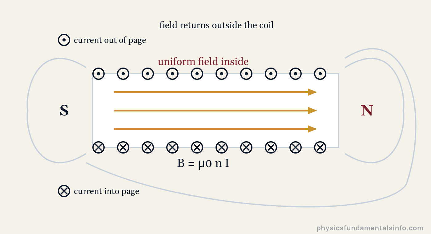
Cross-section of a solenoid. Current flows out of the page along the top wires and into the page along the bottom, so the field inside points from the S end to the N end.
The Solenoid Formula: B = μ0nI
The magnetic field inside a long solenoid is the product of three things: the permeability of free space, the turns per metre, and the current.
| Symbol | Quantity | SI unit |
|---|---|---|
| B | Magnetic flux density inside the coil | tesla (T) |
| μ0 | Permeability of free space, 4π × 10-7 T·m/A | tesla metre per ampere (T·m/A) |
| n | Turns per unit length, n = N / L | per metre (m-1) |
| I | Current in the wire | ampere (A) |
| N | Total number of turns (dimensionless count) | — |
| L | Length of the winding | metre (m) |
A Footnote on μ0 That Older Textbooks Miss
For decades μ0 was defined as exactly 4π × 10-7 T·m/A. That stopped being true in 2019, when the SI was revised and the ampere was pinned to a fixed value of the elementary charge instead.
μ0 is now a measured quantity. The current CODATA value published by NIST is 1.25663706127(20) × 10-6 T·m/A, which differs from 4π × 10-7 only in about the tenth significant figure.
So keep using 4π × 10-7. It is right to nine figures, and no solenoid you wind will be accurate to three.
n Is Turns Per Metre — Not Total Turns
This single confusion costs more exam marks than anything else in the topic. The formula wants n, turns per metre, but the question almost always hands you N, the total count.
So a 500-turn coil wound over 25 cm gives n = 500 / 0.25 = 2000 turns per metre. Miss that division and your answer is out by a factor of the coil’s length in metres — often a factor of four or five.
In practice, write down n as its own line before you touch B. Substituting numbers into the Magnetic Field Calculator is a fast way to check your arithmetic, since it rearranges B = μ0nI for the field, the turns per metre or the electric current.
What the Formula Quietly Assumes
B = μ0nI describes an ideal solenoid: infinitely long, tightly wound, with nothing but air or vacuum inside. Real coils are none of those things, so the formula is an approximation — a very good one, provided the coil is long compared with its width.
- Length much greater than diameter. At ten times longer than it is wide, the centre field is within about 0.5% of μ0nI.
- Turns evenly and tightly spaced. Gaps let field leak sideways between the windings.
- No magnetic core. Slide iron inside and the field multiplies (see below).
- Measured near the middle. Towards the ends the field falls away sharply.
Adding a Magnetic Core
Fill the coil with a ferromagnetic material and the field grows by the relative permeability μr of that material.
Soft iron has a μr in the hundreds or thousands, which is why a nail wrapped in wire lifts paperclips that bare copper coils cannot. There is a ceiling, though: every ferromagnet saturates, typically somewhere near 1.5 to 2 tesla, and beyond that point extra current buys almost no extra field.
How a Solenoid Works
A solenoid works because the magnetic fields of its individual current loops reinforce each other along the axis and cancel each other sideways, leaving one straight, uniform field down the middle.
Picture a single loop first. Its field lines thread through the middle of the loop and flare out around the wire, strongest right at the centre and weakening fast.
Now set a second loop next to the first. Between them, one loop’s returning field points backwards while the other’s forward field points ahead — and the two partly cancel. Down the shared axis, though, both point the same way and add.
Keep stacking. With enough loops, the sideways leakage between neighbours is squeezed out almost entirely, and what survives is a clean axial field of constant strength.
Deriving B = μ0nI With Ampère’s Law
The formal derivation takes four steps and one clever choice of loop. Ampère’s law says that the magnetic field summed around any closed path equals μ0 times the current threading that path.
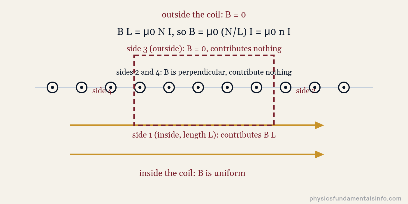
The Ampèrian rectangle. Only the side running inside the solenoid contributes to the integral, which is what makes the derivation so short.
Step 1 — choose the loop. Draw a rectangle that straddles the wall of the solenoid: one long side inside, one long side outside, two short sides crossing the windings.
Step 2 — kill three sides. The outside side sits where the ideal field is zero. The two short sides run perpendicular to the field, so B and the path direction have no component along each other.
Step 3 — evaluate the survivor. Along the inside side, of length L, the field is constant and parallel to the path. That side contributes B·L, and it is the entire integral.
Step 4 — count the current. If N turns pass through the rectangle, each carrying I, the enclosed current is NI. Setting B·L = μ0NI and dividing by L gives B = μ0(N/L)I = μ0nI.
Notice what never appeared: the radius. The algebra never asked how wide the coil was, which is why a narrow solenoid and a fat one with the same turns per metre and the same current produce identical interior fields. MIT’s OpenCourseWare notes work through the same derivation, along with the finite-length case, in Chapter 9, Sources of Magnetic Fields.
Why Is the Field Weaker at the Ends of a Solenoid?
The field at the open end of a long solenoid is almost exactly half its value at the centre. It is one of the tidiest results in magnetostatics, and it follows from simple symmetry.
Stand at the middle of the coil and you have windings pushing field at you from both sides. Stand at the mouth and half those windings have vanished — there is nothing beyond the rim. Half the sources, half the field.
The curve below is computed for a solenoid five times longer than it is wide. The centre sits at 98% of the ideal μ0nI, and both ends land within a whisker of 50%.
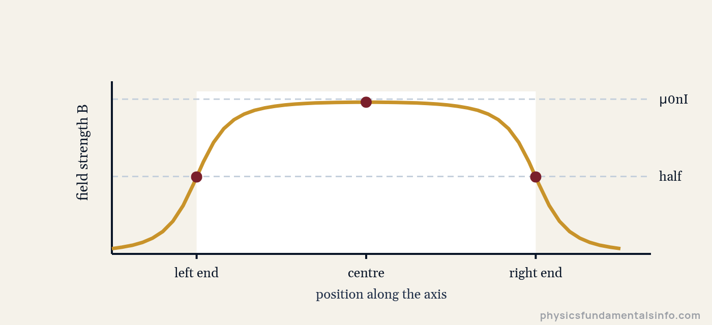
On-axis field of a solenoid whose length is five times its diameter: flat across the middle, dropping to about half at each open end.
This matters more than it looks. If you are building a coil to sit a sample in a known field, put the sample in the middle third — not near the mouth, where a centimetre of position error changes the field by several percent.
Real-World Examples of Solenoids
Solenoids appear anywhere a device needs to convert an electrical signal into either a mechanical push or a controlled magnetic field.
1. Starter Solenoid in a Car
Turning the ignition key sends a small current through a coil, which drags an iron plunger inward. That plunger slams a heavy contact shut, connecting the battery to the starter motor through cables thick enough to carry hundreds of amps — a tiny current switching an enormous one.
2. Valves in Washing Machines and Sprinklers
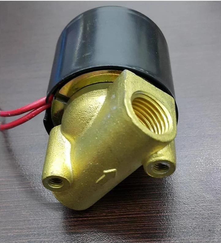
A solenoid valve holds a spring-loaded plug against a water inlet. Energise the coil, the plug lifts, water flows; cut the current and the spring snaps it shut. No moving parts touch the outside world, which is why the seal lasts for years.
3. Door Locks and Doorbells
Electric strike locks use a solenoid to withdraw a bolt when a card is swiped. Old-fashioned doorbells use one to fling a small hammer at a chime bar — press, clunk, ding.
4. MRI Scanners
The bore of an MRI machine is a very large superconducting solenoid, and the uniformity is the entire point. Hydrogen nuclei in tissue only resonate at a sharply defined frequency if the field is the same everywhere, so the field must be flat to a few parts per million across the imaging volume.
5. Loudspeaker Voice Coils
A speaker’s voice coil is a short solenoid sitting in the gap of a permanent magnet. Feed it a rapidly reversing audio signal and it is pushed and pulled dozens to thousands of times a second, dragging the cone with it. This is one of the few solenoids designed to run on alternating current rather than DC.
Solenoid vs Other Current-Carrying Shapes
Bend a current-carrying wire differently and you get a completely different field. The comparison below is the quickest way to see what the solenoid geometry actually buys you.
| Shape | Field formula | Where it applies | Uniform? |
|---|---|---|---|
| Long straight wire | B = μ0I / (2πr) | Distance r from the wire | No — falls as 1/r |
| Single circular loop | B = μ0I / (2R) | At the centre of the loop only | No — drops off fast |
| Solenoid | B = μ0nI | Anywhere well inside a long coil | Yes — the key advantage |
| Toroid | B = μ0NI / (2πr) | Inside the ring, radius r from its centre | No — varies as 1/r |
The toroid is the interesting cousin. Bend a solenoid until its ends meet and the field is trapped entirely inside the ring, leaking almost nothing — but you lose uniformity, because the inner edge of the ring is closer to the axis than the outer edge.
Common Misconceptions About Solenoids
“More turns always means a stronger field”
Not on its own. What matters is turns per metre. Double the turns while doubling the length and n is unchanged, so B is unchanged — you have simply used twice as much wire for the same field.
Wind those extra turns into the same length, though, and the field really does double. The distinction is the whole content of the symbol n.
“A wider solenoid gives a stronger field”
The radius does not appear in B = μ0nI at all. A coil the width of a pencil and one the width of a bucket give the same interior field, provided both have the same turns per metre and current.
Width does change other things — the flux through the coil, the wire length needed, the resistance — but not the field strength inside.
“The field outside a solenoid is exactly zero”
Only for the idealised infinite coil. A real solenoid has ends, and field lines have to return through the outside space to close their loops. That external return field is precisely why a solenoid attracts a compass needle from across the bench and behaves like a bar magnet.
“An iron core multiplies the field without limit”
A core boosts B by μr, but only until the material saturates. Once every magnetic domain in the iron is aligned, there is nothing left to recruit, and further current raises the field only as fast as air would. Most soft irons run out of headroom somewhere around 1.5 to 2 tesla.
How Solenoids Relate to Induction, Inductance and Magnetic Fields
A solenoid sits at the junction of three ideas students usually meet separately, and it is the cleanest object on which to connect them.
First, it is a field source. Everything the magnetic field topic says about forces on moving charges applies inside the coil, with the convenient bonus that B is the same everywhere you might place a charge.
Second, change the current and the flux through the coil changes with it — which is electromagnetic induction waiting to happen. The induced EMF follows Faraday’s law, and because a solenoid’s flux is easy to write down, it is the standard worked example.
Third, that self-induced EMF opposes the change that caused it, which is what we call inductance. A solenoid is the archetypal inductor for exactly this reason.
There is a practical limit lurking here too. You cannot simply crank I upward to get more field, because the winding’s electrical resistance turns that current into heat at a rate proportional to I2, and the insulation has a temperature it will not survive.
Worked Problems
Show Solution
Solution:
Step 1: The field inside a long solenoid is B = μ0nI, where n = N / L.
Step 2: n = N / L = 500 / 0.25 m = 2000 m-1.
Step 3: B = (4π × 10-7 T·m/A)(2000 m-1)(2.0 A) = 5.03 × 10⁻³ T.
Answer: B = 5.0 × 10⁻³ T (5.0 mT)
Show Solution
Solution:
Step 1: Rearrange B = μ0nI for the current: I = B / (μ0n).
Step 2: I = (15 × 10-3 T) / [(4π × 10-7 T·m/A)(1200 m-1)].
Step 3: The denominator is 1.508 × 10⁻³ T·m/A · m-1, so I = 9.95 A.
Answer: I = 9.9 A (2 s.f.)
Show Solution
Solution:
Step 1: Find the required turns per metre first: n = B / (μ0I).
Step 2: n = (8.0 × 10⁻³ T) / [(4π × 10-7 T·m/A)(3.0 A)] = 2122 m-1.
Step 3: Convert to a total count: N = nL = 2122 m-1 × 0.40 m = 849 turns.
Answer: N = 849 turns (about 850)
Show Solution
Solution:
Step 1: At the end of a long solenoid, only half the windings lie to one side, so the field is about half the central value.
Step 2: B_end = ½ B_centre = ½ (5.03 × 10⁻³ T).
Step 3: B_end = 2.51 × 10⁻³ T.
Answer: B = 2.5 × 10⁻³ T (2.5 mT), half the centre value
Show Solution
Solution:
Step 1: Air core: B = μ0nI = (4π × 10-7)(500)(0.50) = 3.14 × 10⁻⁴ T.
Step 2: With a core, B = μrμ0nI, so multiply by μr = 500.
Step 3: B = 500 × 3.14 × 10-4 T = 0.157 T.
Answer: 3.1 × 10⁻⁴ T in air, 0.157 T with the core — a 500-fold increase
Sanity check: 0.157 T is comfortably below iron’s saturation point of roughly 1.5–2 T, so treating μr as constant here is legitimate. Push the current ten times higher and it would not be.
Show Solution
Solution:
Step 1: The total number of turns is unchanged at N = 500; only the length has halved.
Step 2: n = N / L = 500 / 0.125 m = 4000 m-1, double the original 2000 m-1.
Step 3: B = (4π × 10-7)(4000)(2.0) = 1.01 × 10⁻² T.
Answer: The field doubles, from 5.0 mT to 1.0 × 10⁻² T (10 mT)
Show Solution
Solution:
Step 1: Flux through a flat area perpendicular to a uniform field is Φ = BA.
Step 2: B = μ0nI = (4π × 10-7)(2000)(2.0) = 5.03 × 10⁻³ T, and A = πr2 = π(0.020 m)2 = 1.257 × 10⁻³ m2.
Step 3: Φ = (5.03 × 10⁻³ T)(1.257 × 10⁻³ m2) = 6.32 × 10⁻⁶ Wb.
Answer: Φ = 6.3 × 10⁻⁶ Wb (6.3 μWb) per turn