An electromagnet is a magnet created by electric current: current flowing through a coil of wire produces a magnetic field, and an iron core inside the coil multiplies that field many times over. Its strength follows B equals the permeability times turns per metre times current, and it switches off the instant the current does.
Somewhere within a few metres of you right now, a coil of wire is pretending to be a magnet. It is in the little speaker in your phone, in the motor that spins your fan, in the doorbell nobody has rung in weeks.
What makes these coils remarkable is not that they are strong. It is that they are obedient. Cut the current and the magnetism vanishes — which is precisely why a scrapyard crane can pick up a car and then, at the flick of a switch, drop it.
What Is an Electromagnet?
An electromagnet is a device that becomes magnetic only while an electric current flows through it. In its simplest form it is nothing more than a coil of insulated wire, usually wound around a core of soft iron.
The physics underneath is a single, sweeping fact: every electric current produces a magnetic field around itself. A straight wire makes a weak field that circles around it. Coil that same wire into a tight helix — a solenoid — and the loops stack their fields together into something strong and orderly down the middle.
Add an iron core and the field can leap by a factor of hundreds. That combination, coil plus core plus current, is what almost everyone means by “electromagnet”.
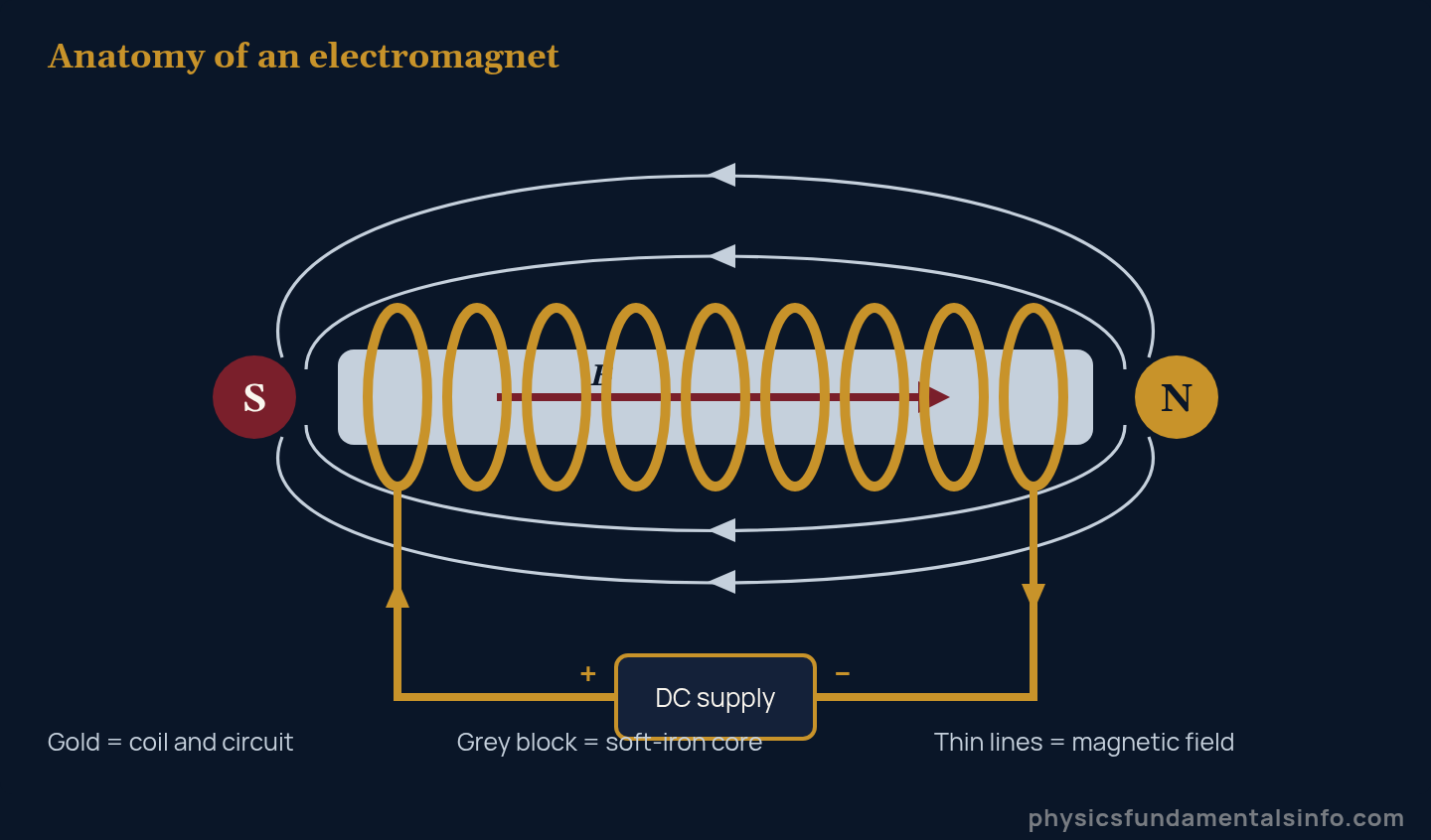
Inside the core the field runs left to right; outside it loops back from N to S. To find which end is north, curl the fingers of your right hand around the coil in the direction of conventional current — your thumb points to the north pole.
The Two Ingredients
- The coil — many turns of insulated wire. Insulation matters: bare wire would short across neighbouring turns and the current would take the shortcut instead of going round.
- The core — a ferromagnetic material, almost always soft iron. “Soft” here is magnetic, not mechanical: it magnetises easily and, crucially, lets go again.
William Sturgeon built the first practical electromagnet in the 1820s. Joseph Henry then made far stronger ones by insulating the wire, which let him wind many close-packed turns without shorting — the same trick every coil still uses today.
The Electromagnet Formula
The magnetic field inside a long, tightly wound coil is given by a formula clean enough to memorise in one sitting.
With a ferromagnetic core in place, the core’s relative permeability multiplies the result:
| Symbol | Quantity | SI unit |
|---|---|---|
| B | Magnetic flux density inside the coil | tesla (T) |
| μ0 | Permeability of free space, 4π × 10−7 | T·m/A (same as N/A2) |
| μr | Relative permeability of the core (air = 1) | no units |
| n | Turns per unit length | turns per metre (m−1) |
| N | Total number of turns | no units |
| L | Length of the coil | metre (m) |
| I | Current through the coil | ampere (A) |
Two features of this equation surprise people. There is no radius in it — a fat coil and a thin coil with the same turns density give the same internal field. And there is no N on its own, only N divided by L.
That second point is the single most common source of wrong answers, so it is worth saying plainly: the field depends on turns per metre, not total turns. Spread 1,000 turns over a metre and you get a tenth of what you get packing them into 10 cm.
Once you have n and I, the arithmetic is quick by hand — or you can run the numbers straight through our Magnetic Field Calculator, which solves B = μ0nI in either direction and shows the working line by line.
A Note on μ0 That Most Textbooks Skip
For decades μ0 was exactly 4π × 10−7, because the old definition of the ampere made it so by decree. Since the 2019 revision of the SI, it is a measured quantity instead.
The CODATA 2022 value from NIST is 1.25663706127 × 10⁻⁶ N/A2, which differs from 4π × 10−7 by roughly one part in ten billion. Keep using 4π × 10−7 — your calculator, your textbook and your examiner all still do.
How Does an Electromagnet Actually Work?
An electromagnet works because moving charge creates a magnetic field, and a coil arranges many such fields so they reinforce each other down its axis. Here is the chain, step by step.
- Current flows. Connect the coil to a supply and charge moves through the wire. The size of that current is set by Ohm’s law: I = V/R, where R is the resistance of the whole length of wire you wound.
- Each turn makes a loop of field. A single current loop produces a field that threads through its centre, like a very weak bar magnet.
- The turns add up. Stack the loops side by side and their fields line up head to tail, producing a strong, near-uniform field down the middle and near-cancellation outside.
- The core amplifies. Iron is full of microscopic magnetic domains pointing in random directions. The coil’s field swings them into alignment, and the aligned iron then contributes a field of its own — usually far larger than the coil’s.
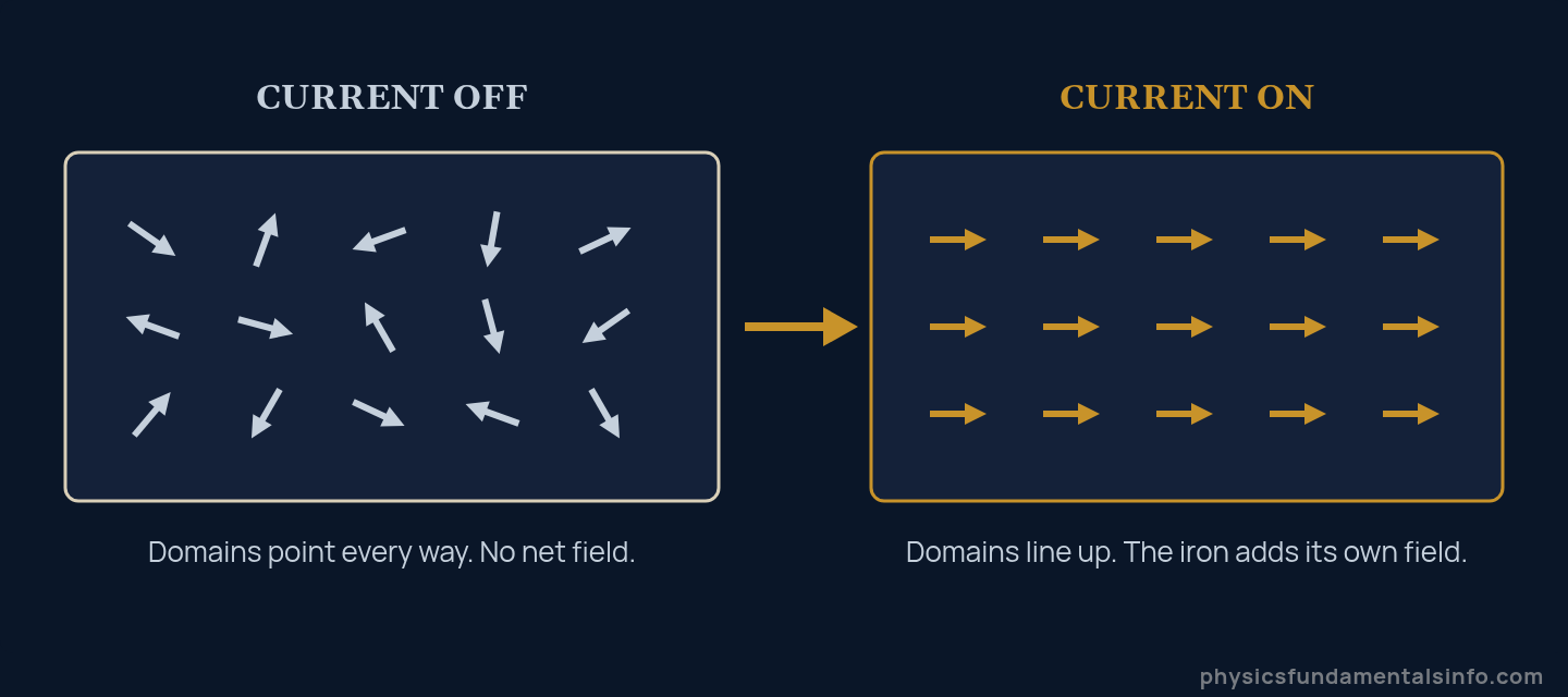
Inside a soft-iron core, the coil’s field acts as a conductor’s baton — the domains fall into step, and their combined field dwarfs the coil’s own.
Soft iron is chosen precisely because it is bad at holding a grudge. When the current stops, the domains scramble again and the magnetism collapses. Hardened steel would keep much of it — useful for making permanent magnets, useless for a crane.
How Do You Make an Electromagnet Stronger?
There are exactly three levers in B = μrμ0nI, and they are wildly unequal in power. Ranked by how much bang they give you:
1. Add a Ferromagnetic Core (Worth Hundreds of Times)
This is not a lever so much as a different machine. Slide a soft-iron rod into an air-cored coil and the field jumps by a factor of μr — typically in the hundreds, sometimes the thousands for specialised alloys.
Be careful with μr values you find quoted, though. Relative permeability is not a fixed material constant: it depends on how hard the material is being driven and on its magnetic history, which is why the same iron is listed as 200 in one book and 5,000 in another.
2. Increase the Turns Density (Worth a Lot, With a Catch)
Pack more turns into the same length and n rises in direct proportion. The catch is that more wire means more resistance, and at a fixed supply voltage more resistance means less current.
Those two effects can cancel exactly — Worked Problem 6 below shows a coil where doubling the turns changes the field by nothing at all. The way round it is to shorten the coil or use thicker wire, not simply to wind more.
3. Increase the Current (Worth Least, Costs Most)
Field is directly proportional to current, so doubling I doubles B — right up until it doesn’t. Two ceilings appear fast.
- Heating. Power dissipated in the coil is I2R, so doubling the current quadruples the heat. This is what actually destroys most homemade electromagnets — melted enamel, then a short, then smoke.
- Saturation. Once every domain in the core is aligned, there is nothing left to align. For iron and silicon steel that ceiling sits at roughly 2 T, and beyond it extra current buys you only warmth.
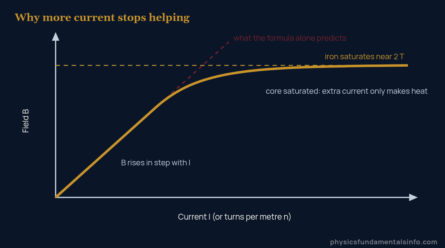
The red dashed line is B = μ0nI taken literally. The gold curve is what a real iron core does — it tracks the prediction, then quietly gives up.
How Strong Is Strong? A Sense of Scale
| Source | Typical field | Notes |
|---|---|---|
| Earth’s magnetic field | 25–65 μT | The baseline a compass reads |
| Air-cored school solenoid | about 5 mT | Roughly 100 times Earth’s field |
| Fridge magnet (at its surface) | a few mT | Permanent, not switchable |
| Same solenoid, iron core | about 1 T | The core does nearly all the work |
| Loudspeaker magnet gap | about 1 T | Drives the voice coil |
| Iron saturation limit | about 2 T | A hard ceiling for iron cores |
| Clinical MRI scanner | 1.5–3 T | Superconducting, no iron core needed |
Use the top row as a sanity check on any answer you calculate. Earth’s field, per NOAA’s geomagnetism data, runs 25–65 μT — so if your homemade coil comes out at 40 T, you have dropped a factor somewhere.
Real-World Examples of Electromagnets
Electromagnets earn their keep wherever magnetism needs to be switched, reversed or precisely dialled. Five places they turn up:
- Scrapyard lifting magnets. A crane picks up several tonnes of steel, swings it over the sorting bay, and cuts the current. The load drops instantly — something no permanent magnet could ever do.
- Electric motors. Coils on the rotor become electromagnets whose poles flip at just the right moment, so they are perpetually chasing the stator’s poles and never catching them.
- MRI scanners. A superconducting coil carries an enormous current with zero resistance, holding 1.5–3 T steady for years without a scrap of iron in the bore.
- Relays and solenoid valves. A small coil current pulls an iron armature, which throws a much larger switch. This is how a 5 V signal from a microcontroller commands a 240 V appliance.
- Loudspeakers and headphones. A coil sitting in a permanent magnet’s field carries the audio signal; the varying force shoves the cone back and forth thousands of times a second.
In practice, one detail decides whether an electromagnet is any good: how little air is left in the magnetic path. Flux crossing an air gap loses most of the benefit of the core, which is why lifting magnets are built with a flat pole face that sits hard against the load.

Electromagnet vs Permanent Magnet: What Is the Difference?
The difference is control. A permanent magnet’s field is baked in at manufacture; an electromagnet’s field is whatever you tell it to be, moment to moment.
| Property | Electromagnet | Permanent magnet |
|---|---|---|
| Source of field | Electric current in a coil | Permanently aligned domains |
| Can it be switched off? | Yes, instantly | No |
| Strength adjustable? | Yes, by varying the current | No, fixed |
| Poles reversible? | Yes, reverse the current | No, only by physically turning it |
| Needs power? | Yes, continuously | No |
| Fails when? | Power cut, or coil overheats | Overheating or a hard knock |
| Practical top field | Tens of tesla with superconductors | Roughly 1 T at the surface |
That “fails when” row is not trivia. A scrapyard magnet dropping its load on a power cut is a genuine safety design problem, which is why some lifting systems carry backup batteries and others use permanent magnets that are mechanically shunted instead.
Common Misconceptions About Electromagnets
“An Electromagnet Needs a Magnet Inside It”
It does not. A coil of wire with nothing in the middle is already a fully functioning electromagnet — weak, but real. The iron core is an amplifier, not the source; unmagnetised iron on its own does nothing at all.
“More Turns Always Means a Stronger Field”
Only if the coil length and the current stay put. Winding extra turns onto the same former adds resistance, which drops the current at a fixed voltage, and the two effects can cancel exactly. Problem 6 below works a case where 400 turns beat 200 turns by precisely zero.
“Just Keep Turning Up the Current”
Two hard limits stop you. The core saturates near 2 T, after which extra current adds essentially nothing to B — and heating scales as I2R, so you hit thermal failure long before you hit anything interesting.
“Any Metal Core Will Do”
Aluminium, copper and brass cores do nothing measurable, because their relative permeability is essentially 1. You need a ferromagnetic material — iron, nickel, cobalt or their alloys. A plain iron nail beats an expensive copper rod every time.
How Electromagnets Connect to the Rest of Electromagnetism
An electromagnet is where three separate ideas meet, which is exactly why exam boards love it.
Running the machine backwards gives you electromagnetic induction: instead of pushing current through a coil to make a field, you move a field near a coil to make current. The size of that induced voltage comes from Faraday’s law, and the two effects are two faces of the same physics.
The field itself, once created, obeys everything in our guide to the magnetic field — including the force F = qvB on any charge that wanders into it, which is what actually spins a motor. Upstream, the electric current you feed the coil is the one quantity in the formula you directly control.
One last connection worth knowing: run an electromagnet on AC and it does not just weaken, it vibrates. The attractive force depends on B2, so it peaks twice per cycle — which is why mains transformers hum at double the supply frequency. Our comparison of AC vs DC current covers why that matters for relay and lock design.
Worked Problems
Show Solution
Solution:
Step 1: For a long air-cored solenoid, B = μ0 n I, where n = N / L.
Step 2: n = 500 / 0.25 m = 2000 turns/m.
Step 3: B = (4π × 10−7 T·m/A)(2000 m−1)(2.0 A) = 5.03 × 10⁻³ T.
Answer: B = 5.0 mT (2 s.f.)
Show Solution
Solution:
Step 1: In a close-packed single layer, each turn occupies one wire diameter, so n = 1 / d.
Step 2: n = 1 / (0.50 × 10⁻³ m) = 2000 turns/m.
Step 3: B = (4π × 10−7)(2000)(1.5) = 3.77 × 10⁻³ T.
Answer: B = 3.8 mT (2 s.f.)
Show Solution
Solution:
Step 1: With a core, B = μr μ0 n I, so the air-core answer is simply multiplied by μr.
Step 2: B = 200 × 5.03 × 10−3 T = 1.005 T.
Step 3: Ratio = 1.005 T / (50 × 10−6 T) = 2.0 × 10⁴.
Answer: B = 1.0 T, about 20,000 times Earth’s field
Show Solution
Solution:
Step 1: Rearrange B = μ0 n I for turns density: n = B / (μ0 I).
Step 2: n = (8.0 × 10⁻³ T) / [(4π × 10−7 T·m/A)(3.0 A)] = 2122 turns/m.
Step 3: N = n L = 2122 m−1 × 0.30 m = 637 turns.
Answer: N is about 6.4 × 10² turns
Show Solution
Solution:
Step 1: Find the current from Ohm’s law: I = V / R = 12 V / 24 Ω = 0.50 A.
Step 2: Turns density n = 400 / 0.050 m = 8000 turns/m.
Step 3: B = μr μ0 n I = (150)(4π × 10−7)(8000)(0.50) = 0.754 T.
Answer: B = 0.75 T (2 s.f.)
Reality note: a real relay has an air gap in its magnetic path, so the measured field would be noticeably lower than this ideal figure.
Show Solution
Solution:
Step 1: Before. I = 6.0 / 4.0 = 1.5 A; n = 200 / 0.10 = 2000 m−1. So B = (4π × 10−7)(2000)(1.5) = 3.77 × 10⁻³ T.
Step 2: After. Resistance doubles to 8.0 Ω, so I = 6.0 / 8.0 = 0.75 A; n = 400 / 0.10 = 4000 m−1.
Step 3: B = (4π × 10−7)(4000)(0.75) = 3.77 × 10⁻³ T. Doubling n while halving I leaves the product nI unchanged.
Answer: No change — B = 3.8 mT in both cases
This assumes the same wire gauge and the same mean turn circumference; a second winding layer sits at a slightly larger radius, so a real rewind is marginally worse, not better.
Show Solution
Solution:
Step 1: Field from the coil alone: B0 = (4π × 10−7)(8000)(2.0) = 2.01 × 10⁻² T = 20.1 mT.
Step 2: Naive prediction with the core: B = 500 × 20.1 mT = 10.1 T.
Step 3: Iron saturates at roughly 2 T. Once every domain is aligned the core cannot contribute more, so B levels off near 2.0 T and the effective relative permeability collapses to about 2.0 / 0.0201 = 100.
Answer: The formula predicts 10.1 T; the real field caps at about 2 T, with μr falling to roughly 100