Kirchhoff’s law comes in two parts: the current law says the currents arriving at any junction equal those leaving it, and the voltage law says the potential differences around any closed loop sum to zero. Written compactly, ΣI = 0 and ΣV = 0 — conservation of charge and conservation of energy, applied to circuits.
Somewhere in every physics course there is a circuit that breaks you. It has two batteries pointing at each other, a resistor shared between two loops, and no amount of squinting turns it into “series” or “parallel”. Ohm’s law, which has served faithfully until this exact moment, simply has nothing to say about it.
That circuit is not a trick. It is the ordinary case — your phone charger, a car’s electrical system, the power supply on your desk — and it is what Kirchhoff’s laws were built for. Two rules. Both of them things you already believe.
What Is Kirchhoff’s Law?
Kirchhoff’s law is a pair of rules for electrical circuits: the current law (KCL) states that the sum of currents at any junction is zero, and the voltage law (KVL) states that the sum of potential differences around any closed loop is zero. Together they let you solve any circuit made of ordinary components, however tangled.
Here is the thing worth noticing. Neither law is really about electricity.
The current law is a statement that charge does not pile up or vanish at a wire junction — whatever arrives must leave, because there is nowhere else for it to go. The voltage law is a statement that if you walk around a closed loop and return to where you started, you are back at the same potential. You cannot gain energy by walking in a circle. Both are conservation laws wearing a circuit diagram as a disguise.
That is why they are so powerful. Conservation of charge and conservation of energy do not care whether your resistors are in series, in parallel, or in a knot no textbook has a name for.
A Note on the Names
The same two laws travel under several names, which trips people up when they compare sources. The current law is also the first law, the junction rule, the node rule, or KCL. The voltage law is also the second law, the loop rule, the mesh rule, or KVL. Same physics, different textbook.
Gustav Robert Kirchhoff announced both laws in 1845, aged 21 and still a student at Albertus University of Königsberg. He developed them in the mathematics-physics seminar run by Franz Neumann and Carl Jacobi, which he attended from 1843 to 1846, and they extended Georg Ohm’s work from single components to whole networks. He graduated in 1847, and later did major work in spectroscopy and black-body radiation. The MacTutor archive at St Andrews carries the fuller biography.
The Kirchhoff’s Law Formulas
Both laws are sums set equal to zero. That is the whole of the notation.
Kirchhoff’s Current Law (KCL) — the junction rule:
The algebraic sum of all currents at a junction is zero. Count currents flowing in as positive and currents flowing out as negative. Equivalently, and more usefully in practice:
Kirchhoff’s Voltage Law (KVL) — the loop rule:
The algebraic sum of all potential differences around any closed loop is zero. Sources count as rises, resistors count as drops, and the signs are set by the direction you walk.
Every Symbol, With Its SI Unit
| Symbol | Quantity | SI unit |
|---|---|---|
| I | Electric current — rate of charge flow | ampere (A) |
| V | Potential difference across a component | volt (V) |
| ε | EMF — the voltage a source supplies | volt (V) |
| R | Resistance | ohm (Ω) |
| Q | Electric charge | coulomb (C) |
| Σ | “The sum of” — add every term, with its sign | — |
Notice that Kirchhoff’s laws never mention resistance. They constrain currents and voltages only. Every loop equation you write becomes solvable because you substitute V = IR for each resistor — so Ohm’s law is the engine and Kirchhoff’s laws are the steering. If you want to check a single V, I or R value while you work, our Ohm’s Law Calculator handles that one substitution instantly; the loop bookkeeping is still yours.
Kirchhoff’s Current Law: The Junction Rule
Kirchhoff’s current law states that the total current flowing into any junction equals the total current flowing out of it. Charge is conserved, and a junction is just a point in a wire — it has no storage.
Think of a road fork. Eight cars per minute arrive; eight cars per minute must leave, split however the roads dictate. Nothing accumulates at the fork itself, because a fork is not a car park.
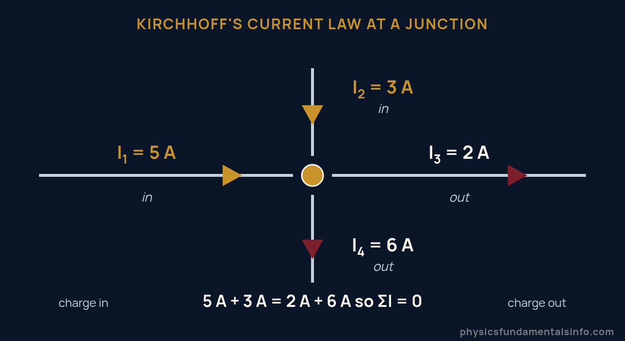
Kirchhoff’s current law at a junction: 5 A and 3 A arrive, 2 A and 6 A leave. Eight amperes in, eight amperes out.
Write it with signs and the two forms agree. Taking “in” as positive: (+5) + (+3) + (−2) + (−6) = 0. Taking in equals out: 5 + 3 = 2 + 6. Use whichever you find less error-prone — most people find “in equals out” harder to get wrong.
Why It Has to Be True
Charge is conserved, and a junction has no capacity to store it. If more charge arrived than left, charge would accumulate at that point in the wire — building an electric field that would immediately push back and stop the imbalance. In practice this happens so fast, and at such vanishingly small charge, that the junction is always balanced for any circuit you will meet in a lab.
That “in practice” hides a real limit, and we return to it below. A capacitor plate is a node where charge genuinely accumulates.
Kirchhoff’s Voltage Law: The Loop Rule
Kirchhoff’s voltage law states that the sum of all potential differences around any closed loop is zero. Every rise is paid for by a drop somewhere else in the loop.
Picture a walk through a hilly town that ends at your front door. Climb, descend, climb again, wander as much as you like — the moment you are back at the door, your net change in altitude is exactly zero. It has to be. It is the same door.
Electric potential behaves identically. A battery lifts charge to a higher potential; resistors let it fall back down. Return to your starting point and the rises and drops must cancel exactly.
The Four Sign Cases — This Is Where Marks Are Lost
KVL is arithmetic. The only difficulty is the sign of each term, and there are exactly four cases to know.
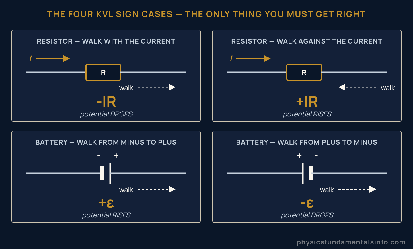
The four sign cases for Kirchhoff’s voltage law. The sign depends on the direction you walk, not on the component.
The rule in one line: the sign is decided by your direction of travel, not by the component. Walk downhill and the term is negative; walk uphill and it is positive.
- Resistor, walking with the current: −IR (you are going downhill, with the flow)
- Resistor, walking against the current: +IR
- Battery, entering − and leaving +: +ε (you climbed the battery)
- Battery, entering + and leaving −: −ε
A common student slip: reading the battery’s own label instead of the direction of travel. The same 12 V battery contributes +12 V or −12 V depending purely on which way your loop happens to cross it. Pick a loop direction, mark it on the diagram, and never change it mid-equation.
KCL vs KVL at a Glance
| Current Law (KCL) | Voltage Law (KVL) | |
|---|---|---|
| Also called | First law, junction rule, node rule | Second law, loop rule, mesh rule |
| Statement | ΣI = 0 at a junction | ΣV = 0 around a loop |
| Applied where | At a point (a node) | Around a path (a closed loop) |
| Conservation of | Charge | Energy |
| Sign set by | Whether current enters or leaves | Your chosen direction of travel |
| Fails when | Charge accumulates at the node | Magnetic flux through the loop changes |
| Equations you get | (number of nodes) − 1 | One per independent loop |
How to Apply Kirchhoff’s Laws in 5 Steps
Apply Kirchhoff’s laws by labelling the currents, writing one junction equation, walking each loop to write its voltage equation, and solving the simultaneous equations. The method never changes, no matter how ugly the circuit.
- Label every branch current — I1, I2, I3… and draw an arrow for each. Guess the directions. Genuinely — guess. The maths will correct you.
- Write the junction equations. With n junctions you get n − 1 useful ones; the last is a repeat of the others and tells you nothing new.
- Choose a loop and a direction. Mark the direction on the diagram with an arrow. Clockwise for everything is a fine habit.
- Walk the loop and write ΣV = 0, using the four sign cases. Substitute V = IR at each resistor.
- Solve the simultaneous equations. A negative answer is not an error — it means that current runs opposite to your arrow, at exactly that magnitude.
You need as many independent equations as unknown currents. Three unknowns, three equations: usually one junction equation and two loop equations.
The Method on a Real Circuit
Here is the canonical case — two batteries, three branches, one shared resistor. It cannot be reduced by series or parallel rules, so Ohm’s law alone is helpless. Kirchhoff’s laws solve it in three lines.
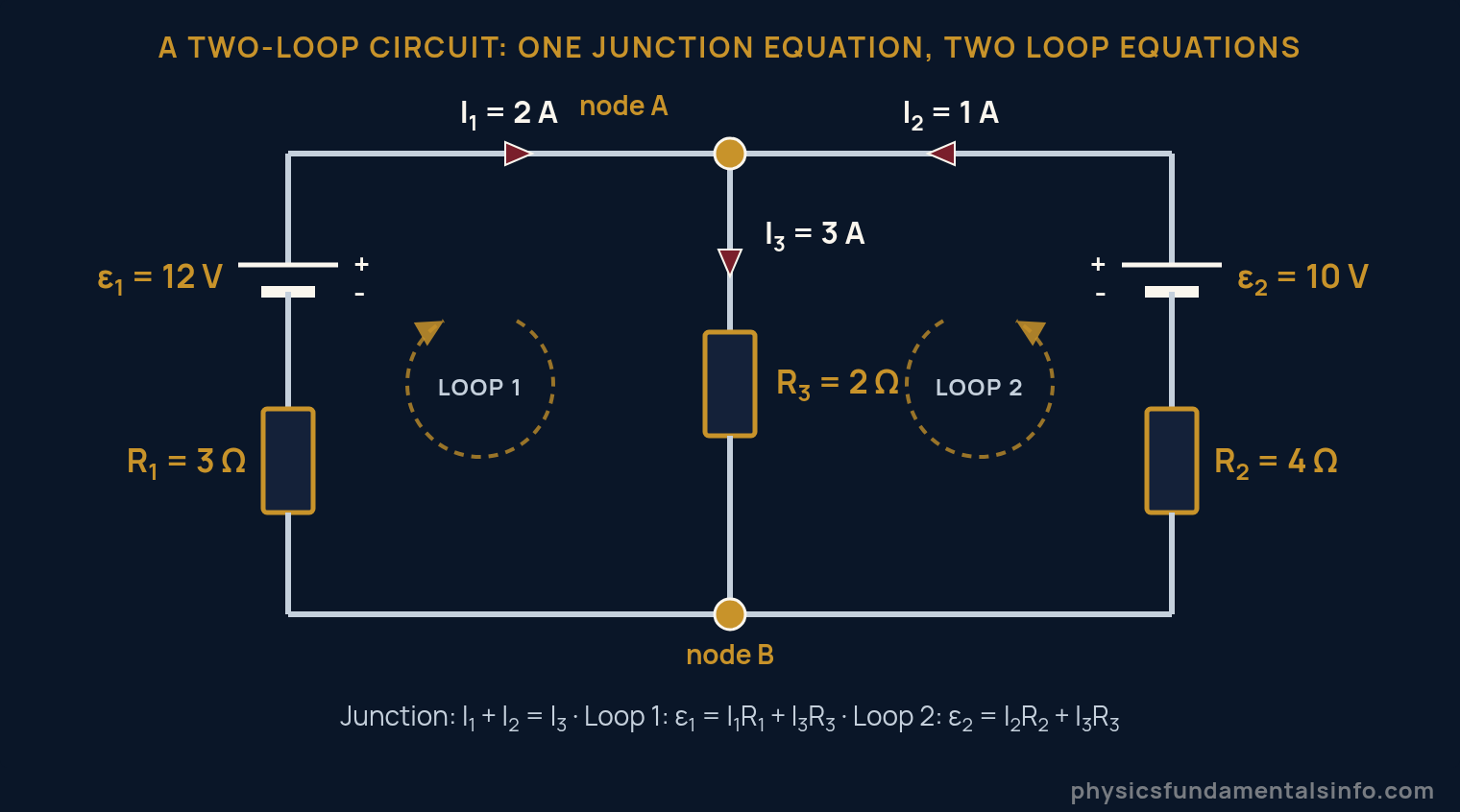
The two-loop circuit solved by Kirchhoff’s law: one junction equation and two loop equations give I1 = 2 A, I2 = 1 A and I3 = 3 A. This is Worked Problem 5 below.
Three unknowns, three equations, no cleverness required. MIT OpenCourseWare’s 8.02 chapter on DC circuits sets out the same procedure formally in its problem-solving strategy section, if you want the university-level statement of it.
Now change the numbers and watch the currents move. The lab below solves the same topology live — drag the EMFs and resistances and see which way the currents actually flow.
Real-World Examples of Kirchhoff’s Laws
Kirchhoff’s laws are used anywhere current has more than one path to take — which is to say, in essentially every circuit built since 1845.
Every circuit simulator you have ever used. SPICE, the engine inside most electronics design software, is at heart a machine that writes Kirchhoff’s current law at every node and solves the resulting matrix. Every chip in your phone was verified this way before it was ever fabricated.
Your car’s electrical system. Alternator and battery both feed the same bus while headlights, ignition and heated seats all draw from it. When the alternator wins, current flows backwards into the battery and charges it — a negative current in exactly the sense the loop rule predicts.
The national grid. Power stations feed a mesh with thousands of nodes and no series-parallel structure at all. Load-flow analysis — the calculation that keeps the lights on — is Kirchhoff’s laws at industrial scale.
The Wheatstone bridge. Five resistors in a diamond, and not one pair is in series or parallel. It is the classic circuit that Ohm’s law alone cannot touch, and it is still the standard way to read a strain gauge or a platinum thermometer.
Battery packs in parallel. Wire two cells with unequal charge together and current flows between them. KCL tells you how much, and it is the reason mixing old and new cells is a bad idea.
Common Misconceptions About Kirchhoff’s Laws
Four beliefs cause most of the lost marks. Each is worth correcting precisely.
“Current gets used up as it goes round”
It does not. Current is charge flow, and charge is conserved — the current leaving a bulb is identical to the current entering it. What gets used up is energy, not charge. The bulb drops the potential; it does not consume the electrons.
“If I guess a current’s direction wrong, my answer is wrong”
This is the big one, and the opposite is true. Guess every direction backwards and the algebra will hand you every current with a minus sign — correct magnitudes, and a sign telling you to flip the arrow. That is not damage control; it is the method working as designed. Worked Problem 6 does this deliberately.
“KVL means the voltages are all equal”
KVL says the rises and drops cancel, not that they match one another. A 12 V battery driving a 3 Ω and a 9 Ω resistor in series gives drops of 3 V and 9 V. Unequal — but they sum to 12 V, and that is what the loop rule demands.
“Kirchhoff’s laws replace Ohm’s law”
They need each other. Kirchhoff’s laws relate currents to currents and voltages to voltages; nothing in them connects the two. Ohm’s law is what turns a loop equation into something solvable. Kirchhoff without Ohm gives you a system with more unknowns than equations.
When Kirchhoff’s Laws Break Down
Kirchhoff’s laws are approximations, and both fail under conditions you can state exactly. This is not a footnote — it is the boundary of the whole lumped-element model, and knowing it separates a student from an engineer.
KCL fails when charge really does accumulate at a node. The law assumes a junction cannot store charge. A capacitor plate is precisely a node that stores charge — which is why, strictly, the current flowing into a capacitor does not equal the current flowing out of that plate. The standard fix is to treat the capacitor as a component with the displacement current running through it, restoring the balance.
KVL fails when magnetic flux through the loop is changing. The loop rule rests on the electric field being conservative — that ∮E·dl = 0 around any closed path. Faraday’s law says otherwise the moment flux changes: ∮E·dl = −dΦ/dt. Put a loop of wire near a transformer and walk it with KVL, and you will get an answer that is simply wrong, because energy is entering the loop through the field rather than through any component.
Both failures have the same root: the lumped-element approximation. Kirchhoff’s laws hold when the circuit is small compared with the wavelength of the signals in it, so that changes propagate across it effectively instantly. Feynman treats exactly this point in his lectures on AC circuits and networks of ideal elements, where the rules are derived as the limit in which fields stay confined to components.
A magnitude check makes it concrete. At 50 Hz mains, the wavelength is thousands of kilometres — a circuit board is nothing, and Kirchhoff’s laws are effectively exact. At 5 GHz the wavelength is about 6 cm, and a 3 cm trace is no longer a wire but an antenna. This is why high-frequency design uses transmission-line theory instead.
So: for every circuit in your course, and almost every circuit on your bench, the laws hold to far better than your components’ tolerances.
How Kirchhoff’s Laws Relate to Ohm’s Law and Energy Conservation
Kirchhoff’s laws are the circuit-sized expression of two conservation laws, and they need Ohm’s law to become solvable. Three familiar ideas, one structure.
Start with Ohm’s law. V = IR describes a single component; it says nothing about how components share a network. Kirchhoff’s laws describe the network but say nothing about components. Neither is complete alone — every loop equation is Kirchhoff’s structure with Ohm’s law substituted in at each resistor.
The voltage law is conservation of energy in disguise. Voltage is work done per unit charge, so ΣV = 0 around a loop says the work done on a charge by the sources exactly equals the work it gives up in the resistors. Take a charge around and hand it back unchanged.
The current law is conservation of charge — the same conserved quantity that Coulomb’s law is built on. Charge cannot be created or destroyed, so it cannot pool at a junction.
Follow the energy one step further and you land in thermodynamics. The energy the resistors take does not disappear; it becomes heat, and it does not come back. That is the first and second laws of thermodynamics arriving in your circuit — KVL is the bookkeeping, and the warm resistor is the receipt.
Worked Problems
Show Solution
Solution:
Step 1: Apply Kirchhoff’s current law. ΣI(in) = ΣI(out).
Step 2: Substitute. 5 A + 3 A = 2 A + I4
Step 3: Solve. 8 A = 2 A + I4, so I4 = 6 A.
Step 4: Check the sign. The result is positive, so the assumed direction was right: it flows out of the junction. Total in = 8 A, total out = 2 + 6 = 8 A. ✔
Answer: I4 = 6 A, flowing out of the junction.
Show Solution
Solution:
Step 1: Walk the loop clockwise, in the direction of the current. Crossing the battery from − to + gives +9 V; each resistor is crossed with the current, so each contributes −IR. KVL: +9 − I(2) − I(4) = 0
Step 2: Collect terms. 9 = I(2 + 4) = 6I
Step 3: Solve. I = 9/6 = 1.5 A
Step 4: Verify the drops. V1 = 1.5 × 2 = 3 V; V2 = 1.5 × 4 = 6 V. Sum = 9 V, exactly the EMF. ✔
Answer: I = 1.5 A; the drops are 3 V and 6 V, summing to the 9 V supplied.
Show Solution
Solution:
Step 1: Apply KVL to each of the three loops. Each resistor sits directly across the battery, so each has the full 12 V across it.
Step 2: Apply Ohm’s law to each branch. I1 = 12/2 = 6 A; I2 = 12/3 = 4 A; I3 = 12/6 = 2 A
Step 3: Apply KCL at the junction where the branches rejoin. Itotal = 6 + 4 + 2 = 12 A
Step 4: Find the equivalent resistance. Req = V/Itotal = 12/12 = 1 Ω
Step 5: Cross-check against the parallel formula. 1/Req = 1/2 + 1/3 + 1/6 = 1, so Req = 1 Ω. ✔ The parallel rule is not a separate law — it is KCL in a hat.
Answer: Itotal = 12 A and Req = 1 Ω.
Show Solution
Solution:
Step 1: Assume the current flows clockwise, driven by the 12 V battery, and walk the loop clockwise. The 12 V battery is crossed − to +, giving +12 V. The 4 V battery is crossed + to −, giving −4 V. Each resistor is crossed with the current: −I(2) each.
Step 2: Write KVL. +12 − 4 − 2I − 2I = 0
Step 3: Collect and solve. 8 = 4I, so I = 2 A
Step 4: Verify. Drops are 2 × 2 = 4 V each. Walking round: 12 − 4 − 4 − 4 = 0. ✔ The 4 V battery is being charged by the 12 V one.
Answer: I = 2 A, flowing clockwise; the 4 V battery is being charged.
Show Solution
Solution:
Step 1: Label and guess. I1 flows from battery 1 into node A; I2 flows from battery 2 into node A; I3 flows from node A down through R3.
Step 2: Apply KCL at node A. I1 + I2 = I3
Step 3: Walk loop 1 (battery 1, R1, R3). 12 = 3I1 + 2I3
Step 4: Walk loop 2 (battery 2, R2, R3). 10 = 4I2 + 2I3
Step 5: Substitute I3 = I1 + I2 into both loop equations.
12 = 3I1 + 2(I1 + I2) = 5I1 + 2I2
10 = 4I2 + 2(I1 + I2) = 2I1 + 6I2
Step 6: Solve the pair. Multiply the first by 3 to match the I2 terms: 36 = 15I1 + 6I2. Subtracting the second equation gives 26 = 13I1, so I1 = 2 A.
Step 7: Back-substitute. 12 = 5(2) + 2I2 gives I2 = 1 A, and KCL then gives I3 = 2 + 1 = 3 A.
Step 8: Check both loops. Loop 1: 3(2) + 2(3) = 6 + 6 = 12 ✔. Loop 2: 4(1) + 2(3) = 4 + 6 = 10 ✔
Answer: I1 = 2 A, I2 = 1 A, I3 = 3 A.
Show Solution
Solution:
Step 1: Assume the same directions as before — both I1 and I2 flowing into node A, I3 flowing out through R3. KCL: I1 + I2 = I3
Step 2: Walk loop 1. 12 = 2I1 + 3I3
Step 3: Walk loop 2. 2 = 4I2 + 3I3
Step 4: Substitute I3 = I1 + I2.
12 = 5I1 + 3I2
2 = 3I1 + 7I2
Step 5: Solve. Multiply the first by 7 and the second by 3, giving 84 = 35I1 + 21I2 and 6 = 9I1 + 21I2. Subtracting leaves 78 = 26I1, so I1 = 3 A.
Step 6: Back-substitute. 12 = 5(3) + 3I2 gives I2 = −1 A, and KCL then gives I3 = 3 + (−1) = 2 A.
Step 7: Read the minus sign. I2 = −1 A means 1 A flows in the direction opposite to the arrow drawn — out of node A and back into battery 2. The 12 V battery is charging the 2 V one. Nothing was done wrong; the algebra simply corrected the guess.
Step 8: Check. Loop 1: 2(3) + 3(2) = 12 ✔. Loop 2: 4(−1) + 3(2) = −4 + 6 = 2 ✔
Answer: I1 = 3 A, I2 = −1 A (1 A flowing the other way, charging battery 2), I3 = 2 A.
Show Solution
Solution:
Step 1: Use P = εI for each source, with the currents from Problem 6.
Step 2: Battery 1 delivers P1 = 12 × 3 = 36 W.
Step 3: Battery 2 gives P2 = 2 × (−1) = −2 W. Negative power for a source means it is absorbing, not delivering — it is being charged at 2 W.
Step 4: Use P = I2R for each resistor.
R1: (3)2 × 2 = 18 W
R2: (−1)2 × 4 = 4 W
R3: (2)2 × 3 = 12 W
Resistor total = 18 + 4 + 12 = 34 W
Step 5: Balance the books. In: 36 W from battery 1. Out: 2 W into battery 2, plus 34 W as heat in the resistors — 36 W total.
Step 6: Note that R2 dissipates 4 W whichever way its current flows, because the current is squared. A negative current still heats a resistor.
Answer: 36 W delivered = 2 W stored in battery 2 + 34 W dissipated as heat. Energy balances exactly, which is KVL in power form.