Electrical resistance is a measure of how strongly a component opposes the flow of electric current, defined as the voltage across it divided by the current through it (R = V/I) and measured in ohms. For a uniform conductor, resistance equals resistivity multiplied by length and divided by cross-sectional area.
Reach behind your desk and feel a phone charger after an hour’s work. It is warm — not because anything is broken, but because something inside it is fighting the current, and losing that fight as heat.
That fight has a name, a symbol and a unit. It also explains why a toaster glows orange while the cable feeding it stays cool, why power stations sit at the end of colossal pylons, and why the wire in your walls is fat, short and made of copper.
What Is Electrical Resistance?
Electrical resistance is the opposition a material or component offers to the flow of electric charge through it. Push charge through anything except a superconductor and something pushes back.
Picture water in a pipe again — the analogy is old because it works. Pressure drives the flow, the pipe’s narrowness fights it, and what you actually get is the compromise. Resistance is the narrowness.
But here is the part worth pausing on. Resistance is not a substance sitting inside the wire; it is a ratio, a bookkeeping of how much push you need for how much flow. Give a component one volt, measure one amp, and you have defined its resistance as exactly one ohm.
The unit is the ohm, symbol Ω, named for Georg Simon Ohm. One ohm is one volt per ampere — and since the 2019 revision of the SI, the ohm is realised in national laboratories from the quantum Hall effect rather than from any physical lump of metal. NIST’s Metrology of the Ohm programme is where that standard actually lives.
The Electrical Resistance Formula: R = V/I
The defining formula for electrical resistance is the voltage across a component divided by the current through it.
- R — resistance, measured in ohms (Ω)
- V — potential difference across the component, measured in volts (V)
- I — electric current through the component, measured in amperes (A)
The units close the loop neatly: 1 Ω = 1 V/A. A component that draws 0.5 A from a 12 V supply has a resistance of 24 Ω, and you can check that in seconds with our Ohm’s Law Calculator if you would rather not reach for a pen.
This equation is the rearranged form of Ohm’s law, and that relationship deserves its own careful treatment. Here, though, R is the star rather than the supporting act — so the interesting question is not how do I find R, but what decides what R is in the first place?
Because R = V/I is a definition, it works on anything: a resistor, a diode, a cucumber. What it does not promise is that the number stays put. For a metal at steady temperature it does. For a filament lamp it climbs as the lamp heats.
Engineers name that distinction. The plain V/I ratio at one operating point is the static resistance; the slope of the current-voltage curve at that same point is the differential resistance. Wikipedia’s overview of electrical resistance and conductance sets the two side by side, together with conductance, the reciprocal quantity you will meet shortly.
What Sets Electrical Resistance? The 4 Key Factors
Four things decide a conductor’s resistance: what it is made of, how long it is, how thick it is, and how hot it is. The first three are bundled into one compact formula.
- R — resistance, in ohms (Ω)
- ρ (rho) — resistivity of the material, in ohm-metres (Ω·m)
- L — length of the conductor, in metres (m)
- A — cross-sectional area, in square metres (m2)
Read the formula as a sentence and it stops being algebra: longer means harder, fatter means easier, and the material sets the exchange rate. If you would rather see where it comes from than take it on trust, the OpenStax chapter on resistivity and resistance at Physics LibreTexts derives it from current density.
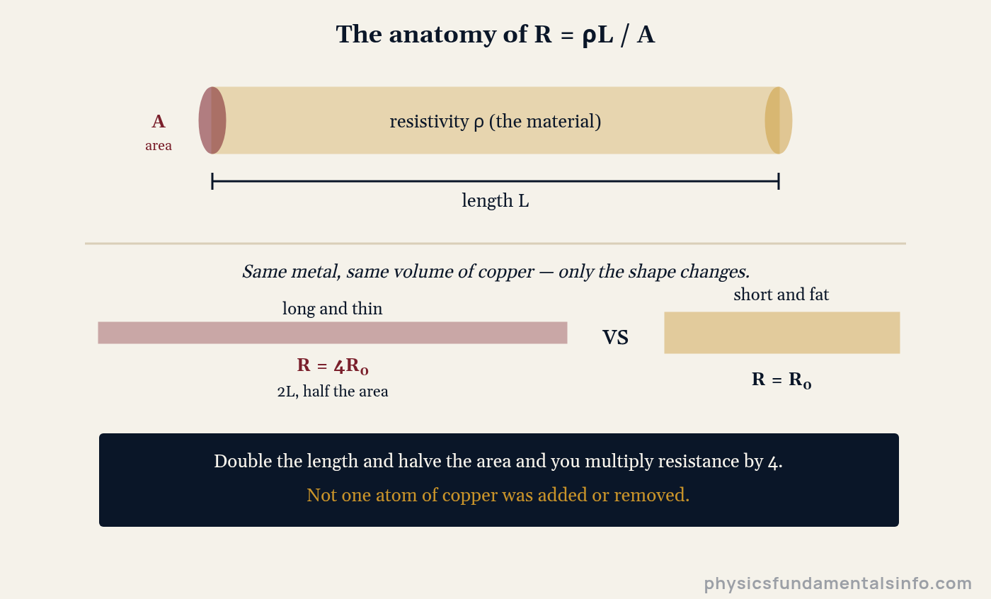
Resistance is set by the material (ρ) and the shape (L and A) together — stretch the same metal and R climbs.
1. The material — resistivity (ρ)
Resistivity is the material’s own contribution, independent of shape. It is why copper wires your house and glass insulates a pylon.
The span is genuinely staggering: from silver at 1.59 × 10⁻⁸ Ω·m to glass at around 1014 Ω·m is roughly twenty-two orders of magnitude — one of the widest ranges of any physical property. Nichrome, the alloy in your toaster, is about 65 times more resistive than copper. That single ratio is why one glows and the other does not.
2. Length (L)
Resistance is directly proportional to length. Double the wire, double the resistance — every extra metre is more lattice for the electrons to bump through.
3. Cross-sectional area (A)
Resistance is inversely proportional to area, and this is where intuition quietly fails. Area depends on the square of the diameter, so doubling a wire’s diameter does not halve its resistance — it quarters it.
4. Temperature (T)
Heat a metal and its resistance rises. The ions vibrate harder, electrons collide more often, and the material fights back more. For modest temperature changes the relationship is close to linear:
- R — resistance at the new temperature, in ohms (Ω)
- R0 — resistance at the reference temperature (usually 20 °C), in ohms (Ω)
- α (alpha) — temperature coefficient of resistance, in per degree Celsius (°C−1)
- ΔT — temperature change from the reference, in degrees Celsius (°C) or kelvin (K)
For copper, α ≈ 3.9 × 10⁻³ °C−1 — about 0.39% per degree. It sounds trivial until a motor winding climbs 50 °C and quietly gains a fifth of its resistance.
Semiconductors do the opposite: warm them and resistance falls, because heat frees more charge carriers. That inversion is the whole basis of the thermistor in your kettle and your car’s coolant sensor — and it is why the difference between heat and temperature is worth getting straight before you trust any resistance figure.
A practical warning worth carrying: the linear formula is reliable for changes of roughly 100 °C or less. Push it to a lamp filament at 2,500 °C and it will mislead you.
Resistance vs Resistivity: The Difference That Trips Students Up
Resistance belongs to an object; resistivity belongs to a material. That one sentence resolves most of the confusion in this topic.
Ask “what is the resistance of copper?” and the question has no answer — you have to say which piece of copper. Ask “what is the resistivity of copper?” and there is a single number, 1.68 × 10⁻⁸ Ω·m, true for every scrap of it at 20 °C.
| Property | Resistance (R) | Resistivity (ρ) |
|---|---|---|
| Belongs to | A specific object or component | A material, whatever its shape |
| SI unit | ohm (Ω) | ohm-metre (Ω·m) |
| Changes with shape? | Yes — depends on L and A | No — intrinsic to the material |
| Changes with temperature? | Yes | Yes |
| Reciprocal quantity | Conductance G = 1/R, in siemens (S) | Conductivity σ = 1/ρ, in S/m |
| Typical question | “What is this wire’s resistance?” | “Is this metal a good conductor?” |
The link between them is the formula you already have. Resistivity plus geometry gives resistance — and rearranging lets you go the other way, measuring ρ from a sample: ρ = RA/L. Georgia State’s HyperPhysics summary of resistance and resistivity is a compact reference if you want the bulk-property view alongside this one.
Here are representative values at 20 °C, with the temperature coefficient that tells you how fast each one drifts.
| Material | Resistivity ρ at 20 °C (Ω·m) | Coefficient α (°C−1) | Why it is used |
|---|---|---|---|
| Silver | 1.59 × 10⁻⁸ | 3.8 × 10⁻³ | Best metallic conductor; specialist contacts |
| Copper | 1.68 × 10⁻⁸ | 3.9 × 10⁻³ | Household wiring — nearly as good, far cheaper |
| Aluminium | 2.65 × 10⁻⁸ | 3.9 × 10⁻³ | Overhead power lines — light enough to span pylons |
| Tungsten | 5.6 × 10⁻⁸ | 4.5 × 10⁻³ | Lamp filaments — survives white heat |
| Nichrome | ≈ 1.1 × 10⁻⁶ | 0.4 × 10⁻³ | Heating elements — resistive and barely drifts when hot |
| Glass | 1010 to 1014 | — | Insulators on pylons and circuit boards |
Treat these as good representative figures rather than gospel — published values shift with purity, alloy composition and the reference you consult.
Notice nichrome’s α. It is roughly a tenth of copper’s, and that stability is the point: a heating element whose resistance barely moves between cold and red-hot draws a predictable current all day long.
Why Does Electrical Resistance Exist?
Resistance exists because moving electrons collide with a vibrating lattice of ions and lose energy to it. The wire is not an open pipe; it is an obstacle course.
Apply a voltage and an electric field appears along the conductor, pushing every free electron — the same electrostatic push described by Coulomb’s law. Each electron accelerates, travels a tiny distance, slams into an ion, and surrenders the speed it just gained.
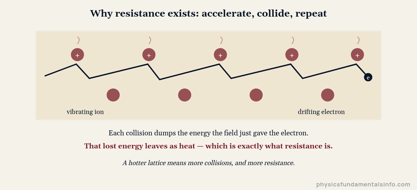
Resistance is billions of tiny collisions per second, converting ordered electrical energy into random thermal motion.
It is a close cousin of mechanical friction, and the parallel runs deep: both oppose motion, both convert organised energy into heat, and neither is a force you can ever quite switch off.
Two consequences fall straight out of this picture. Heat the lattice and collisions multiply, so resistance rises. Lengthen the obstacle course and there are more collisions to survive, so resistance rises again — exactly as R = ρL/A predicted.
Then there is the exception that proves how strange nature can be. Cool certain materials below a critical temperature and resistance does not merely fall — it vanishes, completely, and a current once started will circulate for years without a battery.
Real-World Examples of Electrical Resistance
Resistance is not exam furniture. It is a design constraint that engineers wrestle with daily, and occasionally a safety feature that saves lives.
1. The toaster that glows
A toaster element is a long, thin nichrome ribbon — every term in R = ρL/A pushed deliberately in the direction of more. High ρ, big L, small A. The result is an element hot enough to brown bread while the copper flex behind it stays cool.
2. Why power lines run at 400,000 volts
Transmission losses go as I2R, so halving the current cuts losses fourfold. Since power is voltage times current, the trick is to send it at monstrous voltage and tiny current — which is precisely why pylons exist.
3. The cable that drops your voltage
Run 30 m of 2.5 mm2 copper to a garden workshop and the there-and-back conductor is 60 m — about 0.40 Ω. Draw 13 A through it and you lose over 5 V before the tool even starts. Worked problem 7 does the sum.
4. Thermometers with no mercury
Because resistance tracks temperature so predictably, you can run the logic backwards: measure R, infer T. Platinum resistance thermometers do exactly this, and the thermistor in your car’s coolant sensor is the cheap, twitchy cousin.
5. Why electricians respect wet hands
Dry skin can offer tens of thousands of ohms; wet skin, dramatically less. The mains voltage has not changed — but with R slashed, I = V/R sends far more current through a body that was never designed to conduct it.
Common Misconceptions About Electrical Resistance
“Resistance and resistivity are the same thing”
They are not, and this is the single most common slip in the topic. Resistivity (ρ, in Ω·m) is a property of the material; resistance (R, in Ω) is a property of a particular object cut from it.
Copper has one resistivity. A copper wire has a resistance that depends entirely on how you shaped it — and two wires from the same reel can differ by a factor of a thousand.
“A thicker wire has more resistance — there’s more metal in the way”
The opposite is true. More cross-sectional area means more parallel routes for charge, so resistance falls: R is proportional to 1/A.
Worse, the error usually hides a second one. Because A depends on d2, doubling the diameter quarters the resistance rather than halving it — a mistake that turns a correct method into a wrong answer.
“A resistor’s marked value is its resistance, full stop”
Only at the temperature it was specified at. Every metal resistor drifts with temperature, and components that get hot in normal use drift a lot.
In practice this catches people out with lamps. A filament measures a few ohms cold on a multimeter and runs at ten to fifteen times that when lit — which is exactly why lamps blow at switch-on, when resistance is low and the inrush current is brutal.
How Electrical Resistance Relates to Current, Power and Circuits
Resistance connects to the rest of electricity through two equations you will use constantly. The first gives the current, the second gives the cost.
- P — power dissipated as heat, in watts (W)
- I — current through the component, in amperes (A)
- V — potential difference across it, in volts (V)
- R — resistance, in ohms (Ω)
Every ohm in a circuit is a tollbooth charging energy as heat. Sometimes that is the entire product — a kettle, a toaster, a hair dryer. Usually it is pure waste, and the engineer’s job is to make R as small as economics allows.
Combining resistors follows two rules. In series resistances add (R = R1 + R2 + …), because you have lengthened the obstacle course. In parallel the reciprocals add (1/R = 1/R1 + 1/R2 + …), because you have widened it.
That is not a coincidence — look again at R = ρL/A. Series is the L on top; parallel is the A underneath. Same formula, wearing a different hat.
One habit worth stealing from working engineers: sanity-check the magnitude. Connecting wire should land near a hundredth of an ohm, a kettle element near twenty, your skin in the thousands. If a wire calculation gives you 400 Ω, the physics is fine — a unit conversion is not.
Worked Problems
Method beats answers. Write the formula, substitute with units, then solve — and convert to SI before anything else.
Show Solution
Solution:
Step 1: Resistance is defined as voltage over current, so use R = V / I.
Step 2: Substitute with units: R = 12 V ÷ 0.50 A.
Step 3: Solve: R = 24 V/A = 24 Ω.
Answer: R = 24 Ω
Show Solution
Solution:
Step 1: Convert the area to SI first — this is where most marks are lost. A = 0.20 mm2 = 0.20 × 10⁻⁶ m2 = 2.0 × 10⁻⁷ m2.
Step 2: Use R = ρL / A and substitute: R = (1.1 × 10⁻⁶ Ω·m × 2.5 m) ÷ (2.0 × 10⁻⁷ m2).
Step 3: Solve: R = 2.75 × 10⁻⁶ ÷ 2.0 × 10−7 = 13.75 Ω ≈ 14 Ω.
Answer: R ≈ 14 Ω (a sensible element value — it would draw about 17 A at 230 V)
Show Solution
Solution:
Step 1: R is inversely proportional to area A, and A = πd2/4, so A depends on d2.
Step 2: Doubling the diameter multiplies the area by 22 = 4.
Step 3: Since R is inversely proportional to A, the resistance is divided by 4: R = 4.0 Ω ÷ 4 = 1.0 Ω.
Answer: R = 1.0 Ω (not 2.0 Ω — the classic trap is halving instead of quartering)
Show Solution
Solution:
Step 1: Rearrange R = ρL / A to make ρ the subject: ρ = RA / L.
Step 2: Convert and substitute: A = 0.50 mm2 = 5.0 × 10⁻⁷ m2, so ρ = (0.048 Ω × 5.0 × 10−7 m2) ÷ 1.5 m.
Step 3: Solve: ρ = 2.4 × 10⁻⁸ ÷ 1.5 = 1.6 × 10⁻⁸ Ω·m.
Answer: ρ = 1.6 × 10⁻⁸ Ω·m — consistent with copper (1.68 × 10⁻⁸ Ω·m)
Show Solution
Solution:
Step 1: Use R = R0(1 + αΔT), with ΔT measured from the reference temperature.
Step 2: ΔT = 70 °C − 20 °C = 50 °C. Substitute: R = 20.0 Ω × (1 + 3.9 × 10−3 × 50).
Step 3: Solve: R = 20.0 × (1 + 0.195) = 20.0 × 1.195 = 23.9 Ω.
Answer: R = 23.9 Ω — a 20% rise from warming alone, which is why motor windings are rated hot, not cold
Show Solution
Solution:
Step 1: Volume V = A × L stays constant. If L doubles to 2L, then A must halve to A/2.
Step 2: Start from R = ρL / A and substitute the new values: Rnew = ρ(2L) ÷ (A/2).
Step 3: Simplify: Rnew = 4 × (ρL / A) = 4R. Both changes push resistance the same way, so they multiply.
Answer: The resistance becomes 4 times larger
Show Solution
Solution:
Step 1: Current must travel out and back, so the conductor length is L = 2 × 30 m = 60 m. Missing this halves your answer.
Step 2: A = 2.5 mm2 = 2.5 × 10⁻⁶ m2. Apply R = ρL / A = (1.68 × 10−8 × 60) ÷ (2.5 × 10⁻⁶) = 0.40 Ω.
Step 3: Voltage lost in the cable: V = IR = 13 A × 0.40 Ω = 5.2 V — about 2.3% of a 230 V supply, and heat the cable must shed.
Answer: R ≈ 0.40 Ω, with about 5.2 V lost in the cable