AC vs DC current is the difference between electricity that reverses direction and electricity that does not. Alternating current (AC) flows back and forth, completing 50 or 60 cycles every second in mains supplies. Direct current (DC) flows one way only, at a steady value. AC generates and transmits power efficiently; DC runs batteries, electronics and every USB device.
Look at the plug on your laptop charger. There is a brick partway down the cable, and after an hour of use it is warm. That lump is not packaging — it is a translator, and it exists because the electricity in your wall and the electricity in your laptop are two different animals.
One of them reverses direction a hundred times a second. The other never turns around at all. Every charger, phone and LED bulb in your house is quietly converting between the two, all day, without ever mentioning it.
What Is AC vs DC Current?
Alternating current (AC) reverses its direction of flow many times a second; direct current (DC) flows in one direction only and never reverses. Everything else — the sine wave, the frequency, the RMS rule, the transformers on the pole outside — follows from that single fact.
Direct current: one direction, one value
Wire a torch bulb to an AA cell and the current settles on a value and stays there. Charge leaves one terminal, crosses the filament, returns to the other, and never turns back. Plot it against time and you get a horizontal line.
That flatness is the whole appeal. A microprocessor, an LED, a lithium cell — every one of them wants a voltage that sits still and behaves.
Alternating current: a flow that keeps changing its mind
Now switch on a lamp. The current in that flex rises to a peak, falls back through zero, reverses, reaches an equal peak the other way, and returns — over and over, 50 times a second across most of the world and 60 times a second in North America.
Each round trip is one cycle, and the number of cycles per second is the frequency, measured in hertz (Hz). At 50 Hz a single cycle takes 20 milliseconds, which is why a filament bulb never has time to cool between reversals and simply looks steady.
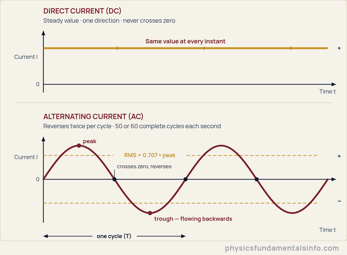
The same idea drawn twice: DC holds one value in one direction, while AC sweeps between equal and opposite peaks — and the number written on the socket is the RMS level, not the peak.
The AC vs DC Current Formulas
Current itself is defined identically for both. It is the amount of charge passing a point each second, and that definition does not care which way the charge is heading.
- I — current, in amperes (A)
- Q — charge passing a point, in coulombs (C)
- t — time taken, in seconds (s)
For DC that is the end of the story: one number, good all day. If you want the arithmetic done for you, our Electric Current calculator rearranges I = Q/t for current, charge or time and counts the electrons involved.
AC needs a second equation, because the current is a moving target. A mains supply is a sine wave, so its instantaneous value depends on where you are in the cycle.
- i(t) — instantaneous current at time t, in amperes (A)
- Ipeak — peak (maximum) current, in amperes (A)
- f — frequency, in hertz (Hz)
- t — time, in seconds (s)
The RMS rule: why 230 V is not the peak
A quantity that swings from +325 V to −325 V and averages exactly zero is useless for describing a kettle. So AC is quoted by its root-mean-square (RMS) value: square the waveform, average that over a whole cycle, then take the square root.
Squaring is the trick. It makes the negative half positive, so the backward flow counts as work done rather than cancelling the forward flow. For a sine wave the average of sin2 over a full cycle is exactly 0.5, and taking the square root of a half gives the factor everyone memorises.
- Vrms, Irms — RMS (effective) voltage in volts (V) and current in amperes (A)
- Vpeak, Ipeak — the maximum values reached each cycle, in volts (V) and amperes (A)
- sqrt(2) ≈ 1.414, so 1/sqrt(2) ≈ 0.707 — this factor applies to sine waves only
Here is what that number actually means. An RMS value is defined so that the AC supply heats a resistor by exactly as much as a DC supply of the same figure would — 230 V RMS delivers the same average power as a 230 V battery.
That equivalence is why Ohm’s law survives the jump to AC untouched, provided every quantity you put into it is an RMS value. Georgia State University’s HyperPhysics makes the same point from the circuit side: a resistor’s opposition to AC is simply its DC resistance, once effective values are used.
- Pavg — average power delivered to a resistive load, in watts (W)
- Vrms, Irms — RMS voltage (V) and RMS current (A)
A common student slip is to multiply the peak voltage by the peak current and call it power. That answer is exactly twice too large, every time.
How AC and DC Are Actually Made
AC comes out of anything that spins; DC comes out of anything that pushes. That is the shortest honest summary of where the two kinds of current are born, and it explains why neither one was really a design choice.
A generator makes a sine wave by accident of geometry
Spin a coil of wire between the poles of a magnet. The magnetic flux threading that coil rises and falls as it turns, and a changing flux induces a voltage across the ends — Faraday’s law of induction.
Because the coil’s orientation is following a rotation, the induced voltage traces the projection of that rotation onto a line. A circle seen edge-on is a sine wave. Half a turn later the coil faces the opposite way and the voltage flips sign.
Nobody sat down and chose the alternation. It falls straight out of the turning.
Batteries, rectifiers and inverters
A battery has no rotation and no reversal. A chemical reaction shoves electrons out of one terminal and pulls them back into the other, and it will keep pushing that way until the chemistry runs down. Solar cells do the same job with photons instead of chemistry. Both are DC by construction.
Traffic between the two worlds runs in both directions, and the two devices that manage it are worth knowing by name:
- Rectifier — converts AC to DC. Diodes let current pass one way only, so the negative halves of the wave are flipped or blocked and then smoothed. This is what lives inside the warm brick on your charger.
- Inverter — converts DC to AC. It chops and shapes a steady DC voltage into something the grid will accept, which is how a rooftop solar array or an electric car can push power back into the mains.
In practice almost nothing you own is purely one or the other. The socket is AC, the chip is DC, and there is a rectifier somewhere in between doing the work.
AC vs DC Current: 7 Differences Side by Side
AC and DC differ in seven ways that matter in practice: direction, waveform, frequency, what the quoted voltage means, how easily the voltage can be changed, where each one comes from, and how far each can be sent economically.
| Property | Alternating Current (AC) | Direct Current (DC) |
|---|---|---|
| 1. Direction of flow | Reverses periodically — twice in every cycle | One direction only; never reverses |
| 2. Shape on a graph | A sine wave that crosses zero twice per cycle | A flat horizontal line above zero |
| 3. Frequency | 50 Hz or 60 Hz on mains supplies | 0 Hz — there is no cycle to count |
| 4. What the quoted voltage means | The RMS value; the peak is 1.414 times higher | The actual value, at every instant |
| 5. Changing the voltage | A transformer does it cheaply and with very little loss | Needs switching electronics — a DC-DC converter |
| 6. Typical sources | Power-station alternators, wall sockets, generators | Batteries, solar cells, USB ports, car electrics |
| 7. Long-distance transmission | The grid standard — stepped up to hundreds of kilovolts | HVDC wins on very long links and undersea cables |
Row four is the one that catches people out in exams, and row five is the one that decided the shape of the modern world.
Why the Grid Runs on AC but Your Devices Run on DC
The grid runs on AC because a transformer can change an AC voltage almost losslessly, and high voltage is the only affordable way to move power a long way. Your devices run on DC because transistors, LEDs and batteries all need a voltage that holds still.
The villain in transmission is the resistance of the cable itself. Push current through it and some of your power is spent warming the countryside.
- Ploss — power wasted as heat in the line, in watts (W)
- I — current in the line, in amperes (A)
- R — total resistance of the line, in ohms (Ω)
Notice the square. Loss depends on current, not on voltage — and current is squared. So if you deliver the same power at a hundred times the voltage, the current drops by a factor of a hundred and the waste drops by a factor of ten thousand.
Every watt burnt in those cables is energy somebody paid to generate and then never sold. That is the entire economic argument, in one squared term.
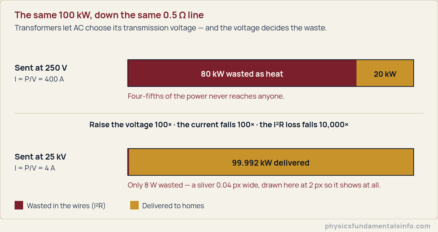
Same power, same cable, two choices of voltage. At 250 V the line eats four-fifths of what you generated; at 25 kV it eats eight watts.
Which brings us to the transformer. Wind two coils onto one iron core, feed the first with AC, and the changing flux induces a voltage in the second — scaled by nothing more exotic than the ratio of the turns.
- Vp, Vs — primary and secondary voltage, in volts (V)
- Np, Ns — number of turns on the primary and secondary coils (a pure number, no units)
Now the punchline. A transformer needs a changing flux to do anything at all. Feed one with steady DC and, after a brief switch-on twitch, it just sits there: a warm lump of copper and iron.
That one limitation settled the argument in the 1890s. The US Department of Energy’s account of the War of the Currents records the turning point: at the 1893 Chicago World’s Columbian Exposition, General Electric quoted $554,000 to light the fair with Edison’s DC and lost to Westinghouse, who did it for $399,000 using Tesla’s AC. On 16 November 1896, Buffalo was lit by alternating current generated at Niagara Falls.
DC could not have made that trip. Not because it was worse electricity — because in 1896 nobody knew how to change its voltage.

Real-World Examples of AC and DC Current
Most homes run both kinds of current simultaneously, separated by a few centimetres of plastic. Five everyday cases make the split obvious.
- Your wall socket — AC. Around 230 V at 50 Hz across Europe, the UK, India and Pakistan; 120 V at 60 Hz in North America; 100 V in Japan, at 50 Hz in the east of the country and 60 Hz in the west.
- Your phone — DC. A USB port supplies a steady 5 V. The charger is a rectifier that turns the wall’s alternating supply into something the battery can accept.
- Your car — both, quietly. The 12 V battery and everything it feeds are DC, but the alternator under the bonnet actually generates AC and rectifies it on the spot with diodes.
- Rooftop solar — DC becoming AC. Panels produce DC because photons only push one way. An inverter converts it before it reaches your consumer unit or the grid.
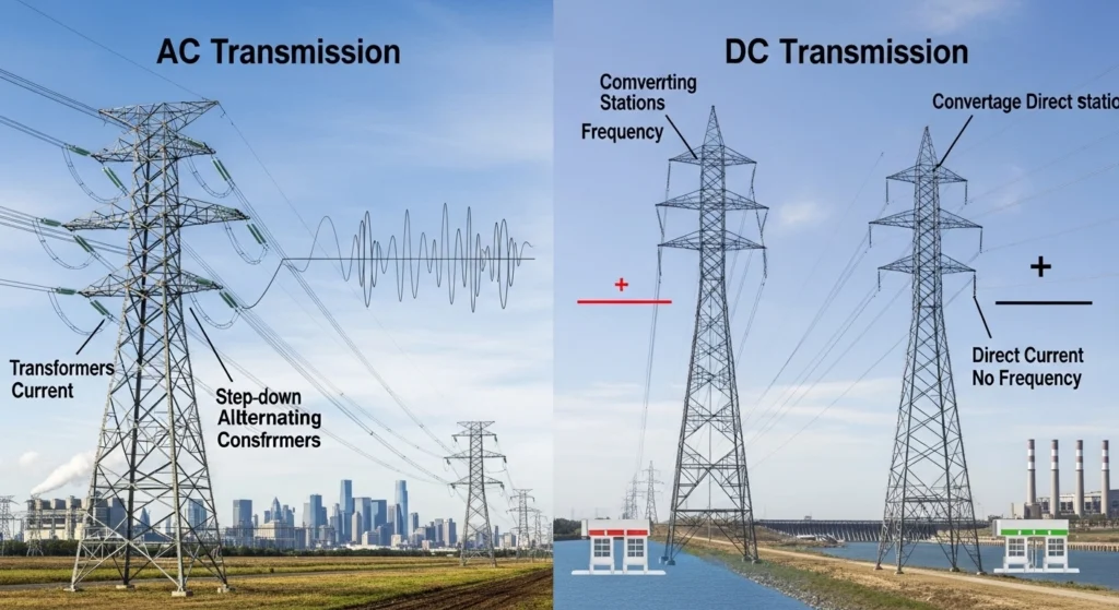
- Undersea and cross-country links — DC again. Beyond a few hundred kilometres, and for almost any submarine cable, high-voltage DC becomes the cheaper option, so the grid converts, ships the power as DC, then converts back.
The pattern is worth naming: AC for moving power, DC for using it. The charger in the middle is the tax you pay for living in both worlds.
Common Misconceptions About AC vs DC Current
Four beliefs about AC vs DC current are wrong often enough to cost marks and, occasionally, equipment.
Myth 1: “230 V is the peak voltage of the mains”
It is not. 230 V is the RMS value, and the waveform actually swings up to 325 V one way and 325 V the other — a peak-to-peak span of about 651 V.
This is not academic. Insulation, capacitors and rectifier diodes have to survive the peak, not the number printed on the socket. In practice a designer who specifies parts for 230 V will watch them fail.
Myth 2: “AC reverses 50 times a second”
It reverses 100 times a second. A 50 Hz supply completes 50 cycles each second, and every cycle contains two reversals: once as the current passes through zero going negative, once on the way back.
At 60 Hz it is 120 reversals a second. Count cycles or count reversals — just do not swap the two.
Myth 3: “The electrons in your socket travel from the power station”
They travel almost nowhere. In a 1.5 mm2 copper flex carrying 5 A at 50 Hz, the electrons shuffle back and forth with an amplitude of roughly one micrometre — a thousandth of a millimetre. They jiggle on the spot and get nowhere.
Even on DC the drift is glacial, a fraction of a millimetre per second. What actually races down the cable is the electromagnetic field, at a good fraction of the speed of light. The electrons are the medium, not the messenger.
Myth 4: “AC won, so DC is obsolete”
DC never left, and it is gaining ground. Every phone, laptop, LED, data-centre server and electric vehicle runs on DC internally, and solar panels generate it directly.
The DOE’s own account of the War of the Currents notes that direct current has been enjoying a revival. The honest verdict is that AC did not beat DC — the two divided the work, and the boundary between them is still moving.
How AC vs DC Current Relates to Ohm’s Law, Frequency and Induction
AC and DC obey exactly the same physics; AC simply adds a clock to it. Three neighbouring ideas do most of the connecting work.
Frequency and period
The only new number AC introduces is how often it repeats, and that comes straight from the frequency formula, f = 1/T. A 50 Hz supply has a period of 20 ms; a 60 Hz supply, 16.7 ms. DC is simply the f = 0 case — a wave with nothing left to repeat.
Simple harmonic motion
The mains sine wave is not a coincidence or a convenience. It is simple harmonic motion wearing electrical clothing: a rotating generator projected onto one axis, exactly as a pendulum’s swing is a circle seen edge-on.
That is why the RMS factor of 0.707 is specific to sine waves. Feed a square wave in and the ratio changes, because the maths was never about electricity — it was about the shape.
Ohm’s law and induction
Ohm’s law needs no modification for AC across a resistor, provided you keep every value in RMS. Add coils or capacitors and it generalises to impedance, where the current no longer peaks at the same instant as the voltage.
Induction is the deeper link. It is what builds AC in the generator, what lets the transformer rescale it, and what makes an induction motor turn — three jobs steady DC cannot do at all.
Worked Problems
Show Solution
Solution:
Step 1: Current is the rate of charge flow, I = Q / t, so Q = I × t.
Step 2: Convert the time first: t = 2.0 min × 60 s/min = 120 s. Then Q = 0.30 A × 120 s.
Step 3: Q = 36 C. The current holds one value in one direction, so it is direct current.
Answer: Q = 36 C, and the current is DC.
Show Solution
Solution:
Step 1: Period and frequency are reciprocals, T = 1 / f.
Step 2: T = 1 / 50 Hz = 0.020 s = 20 ms.
Step 3: Each cycle contains two reversals, so reversals per second = 50 × 2 = 100.
Answer: T = 20 ms, and the current reverses 100 times per second (not 50).
Show Solution
Solution:
Step 1: The rated figure is RMS, so Vrms = Vpeak / sqrt(2), which rearranges to Vpeak = Vrms × sqrt(2).
Step 2: Vpeak = 230 V × 1.414 = 325.3 V.
Step 3: The wave reaches that peak on both sides of zero, so Vpp = 2 × 325.3 V = 650.5 V.
Answer: Vpeak = 325 V and Vpp = 651 V (3 s.f.).
Show Solution
Solution:
Step 1: For a resistive load, Pavg = Vrms × Irms, so Irms = Pavg / Vrms.
Step 2: Irms = 60 W / 230 V = 0.2609 A. Ohm’s law then gives R = Vrms / Irms = 230 V / 0.2609 A = 881.7 Ω.
Step 3: Ipeak = Irms × sqrt(2) = 0.2609 A × 1.414 = 0.3689 A.
Answer: Irms = 0.261 A, R = 882 Ω, Ipeak = 0.369 A (3 s.f.).
Show Solution
Solution:
Step 1: Find the current from I = P / V, then the loss from Ploss = I2 × R.
Step 2: At 250 V: I = 100 000 W / 250 V = 400 A, so Ploss = (400 A)2 × 0.50 Ω = 80 000 W.
Step 3: At 25 kV: I = 100 000 W / 25 000 V = 4.0 A, so Ploss = (4.0 A)2 × 0.50 Ω = 8.0 W.
Answer: 80 kW is lost at 250 V (80% of the power); only 8.0 W is lost at 25 kV (0.008%). Raising the voltage 100 times cut the waste 10 000 times.
Show Solution
Solution:
Step 1: The turns ratio matches the voltage ratio, Vs / Vp = Ns / Np, so Ns = Np × (Vs / Vp).
Step 2: Ns = 5000 × (220 V / 11 000 V) = 5000 × 0.020.
Step 3: Ns = 100 turns. On steady DC the flux in the core is constant, and a constant flux induces no emf, so the secondary voltage is zero once the switch-on transient dies away.
Answer: Ns = 100 turns; on DC the output is 0 V, because transformers need a changing flux.
Show Solution
Solution:
Step 1: Convert to SI and find the peak current: A = 1.5 mm2 = 1.5 × 10⁻⁶ m2, and Ipeak = 5.0 A × sqrt(2) = 7.071 A.
Step 2: Drift speed comes from I = n × e × A × v, so vpeak = Ipeak / (n × e × A) = 7.071 / (8.5 × 1028 × 1.60 × 10−19 × 1.5 × 10−6) = 3.46 × 10⁻⁴ m/s.
Step 3: The drift is sinusoidal, so its displacement amplitude is vpeak / ω, where ω = 2πf = 2π × 50 = 314 rad/s. Amplitude = 3.46 × 10⁻⁴ / 314 = 1.10 × 10⁻⁶ m.
Answer: vpeak = 3.46 × 10⁻⁴ m/s (0.346 mm/s), and the electrons oscillate with an amplitude of just 1.10 μm.