The tangential acceleration simulator is for the bend taken while the speed is still changing — the case ac = v2/r cannot describe on its own. Drag four sliders — the speed, the bend radius, the tangential acceleration and the grip coefficient — and read what the manoeuvre asks of the tyres off four cards and nine cells. Start from one of the six preset cases below, then change one thing at a time. The rest of the page names every control and readout, tabulates all six presets as the lab printed them, and says which canvas lengths may be compared and which may not.
Tangential Acceleration: When the Bend Is Not the Whole Story
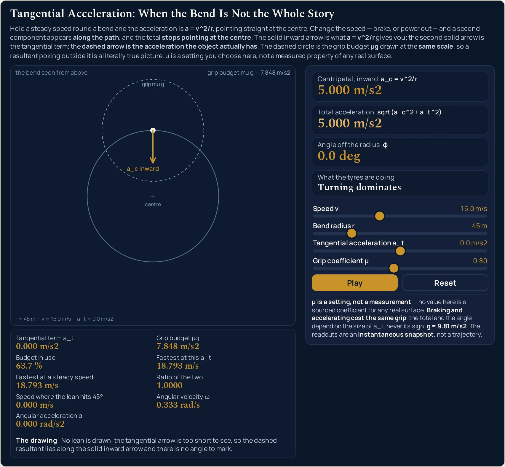
Hold a steady speed round a bend and the acceleration is a = v^2/r, pointing straight at the centre. Change the speed — brake, or power out — and a second component appears along the path, and the total stops pointing at the centre. The solid inward arrow is what a = v^2/r gives you; the second solid arrow is the tangential term; the dashed arrow is the acceleration the object actually has. The dashed circle is the grip budget μg drawn at the same scale, so a resultant poking outside it is a literally true picture. μ is a setting you choose here, not a measured property of any real surface.
Tangential term a_t0.000 m/s2
Grip budget μg7.848 m/s2
Budget in use63.7 %
Fastest at this a_t18.793 m/s
Fastest at a steady speed18.793 m/s
Ratio of the two1.0000
Speed where the lean hits 45°0.000 m/s
Angular velocity ω0.333 rad/s
Angular acceleration α0.000 rad/s2
The drawingNo lean is drawn: the tangential arrow is too short to see, so the dashed resultant lies along the solid inward arrow and there is no angle to mark. Its tip falls inside the dashed grip circle.
Centripetal, inward a_c = v^2/r
5.000 m/s2
Total acceleration sqrt(a_c^2 + a_t^2)
5.000 m/s2
Angle off the radius φ
0.0 deg
What the tyres are doing
Turning dominates
Speed v15.0 m/s
Bend radius r45 m
Tangential acceleration a_t0.0 m/s2
Grip coefficient μ0.80
μ is a setting, not a measurement — no value here is a sourced coefficient for any real surface. Braking and accelerating cost the same grip: the total and the angle depend on the size of a_t, never its sign. g = 9.81 m/s2. The readouts are an instantaneous snapshot, not a trajectory.
Load a real case on the sliders
Each button presses the lab’s own Reset and then writes all four sliders, so every load starts from the same place and a running animation is stopped before the new values land. Work down the list: the first two are the same bend at the same speed, with only the tangential slider moving between them. Every case is named after the manoeuvre rather than a surface, because the grip coefficient here is a setting you choose and nothing on this page measures a road.
Pick a case above, or drag the four sliders yourself.
What Is the Tangential Acceleration Simulator?
The tangential acceleration simulator is a free interactive physics lab that runs in your browser, with nothing to install and no sign-up. It draws one bend seen from above and puts the acceleration on it: a solid arrow pointing inward at the centre for ac = v2/r, a second solid arrow along the path for the tangential term, and a dashed resultant between them, all three at one shared scale.
A light dashed circle centred on the object is the grip budget μg, drawn at that same scale, so a resultant reaching outside it is a literally true picture of a manoeuvre asking for more grip than the setting supplies.
Four sliders set the speed from 0 to 40 m/s, the bend radius from 5 to 200 m, the tangential acceleration from -8 to 8 m/s2 and the grip coefficient from 0.2 to 1.5. Four cards answer with the centripetal part, the total acceleration sqrt(ac2 + at2), the angle that total leans off the inward radius, and a phrase naming what the tyres are doing.
Nine smaller cells carry the tangential term, the grip budget, the fraction of it in use, the fastest speed this bend allows at that tangential acceleration and at a steady speed, the ratio of the two, the speed at which the lean reaches 45 degrees, the angular velocity and the angular acceleration. A sentence strip headed The drawing says what is actually on the canvas, Play carries the object round the bend, and Reset restores 15.0 m/s, 45 m, 0.0 m/s2 and 0.80.
| Control | Range | Step |
|---|---|---|
| Speed | 0 to 40 m/s | 0.5 m/s |
| Bend radius | 5 to 200 m | 1 m |
| Tangential acceleration | -8 to 8 m/s2 | 0.1 m/s2 |
| Grip coefficient | 0.2 to 1.5 | 0.05 |
How to use the tangential acceleration simulator
- Start from the state it opens in. The lab boots on Speed v 15.0 m/s, Bend radius r 45 m, Tangential acceleration a_t 0.0 m/s2 and Grip coefficient μ 0.80, with Centripetal, inward and Total acceleration both reading 5.000 m/s2. Reset returns all four sliders to exactly that and stops the motion if it is running.
- Set the speed. Speed v runs from 0 to 40 m/s in steps of 0.5 and is squared inside the inward part, so it is the slider the inward arrow answers to most sharply. Take it to 0.0 m/s and that arrow has no length left to draw, which is a state the panel still reports in full.
- Set the bend radius. Bend radius r runs from 5 to 200 m in steps of 1 and divides the inward part, so a tighter bend at the same speed raises it. The drawn circle keeps its size on screen because the path is always scaled to fit; the radius you chose is printed under the canvas instead.
- Set the tangential acceleration. Tangential acceleration a_t runs from −8 to 8 m/s2 in steps of 0.1, negative for braking and positive for powering out, and it is the slider that makes this lab different from the circular motion lab. Moving it off zero is what brings the second solid arrow, the dashed resultant and the angle marker onto the canvas together.
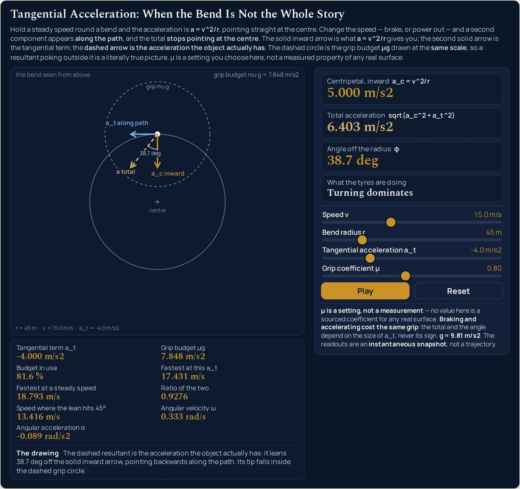
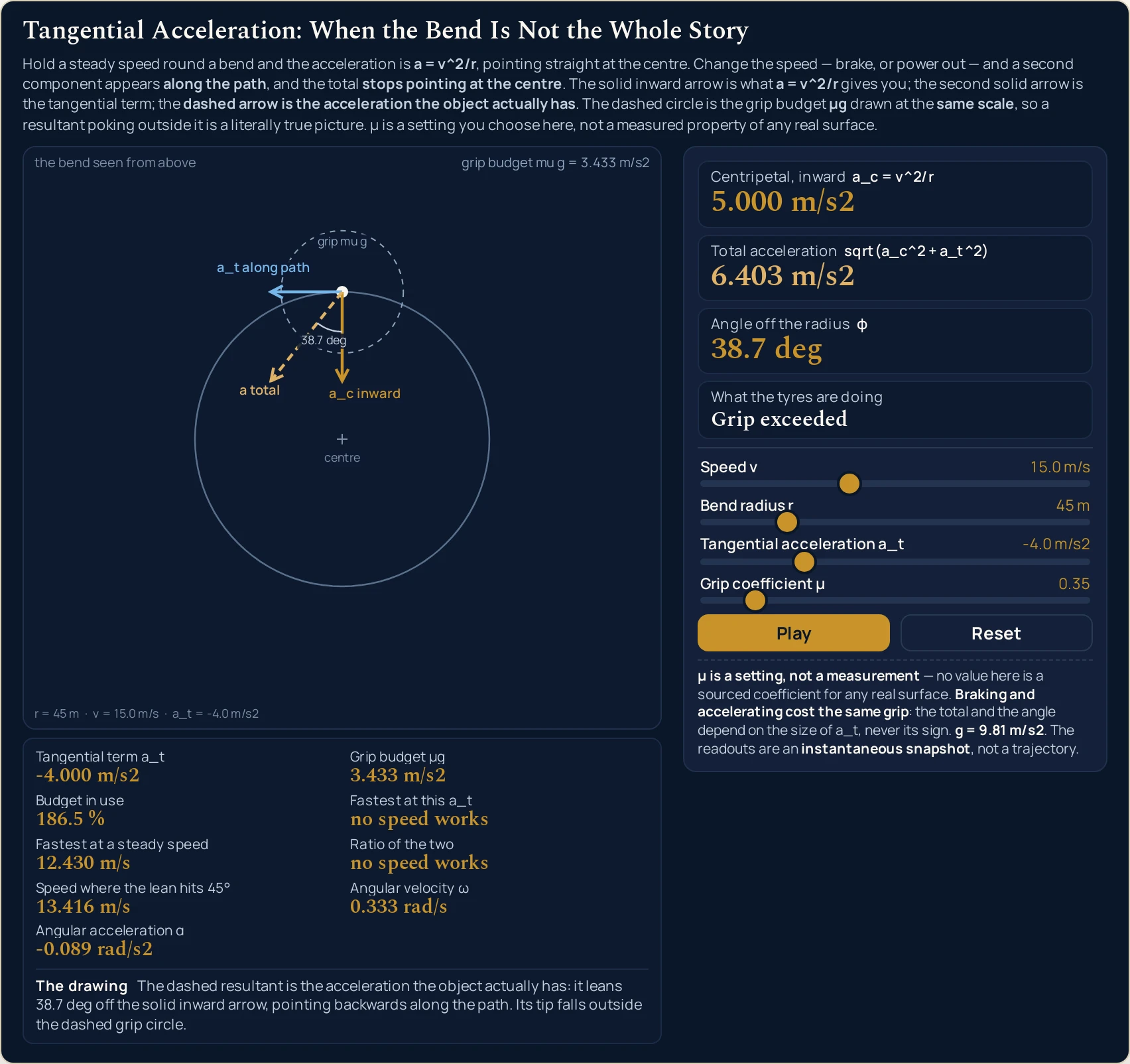
- Set the grip coefficient. Grip coefficient μ runs from 0.2 to 1.5 in steps of 0.05 and changes no acceleration at all: the total stays 6.403 m/s2 on the braking case whether it sits at 0.80 or 0.35. What it moves is the Grip budget μg cell, from 7.848 m/s2 to 3.433 m/s2, and with it the whole scene’s scale.
- Read the four cards down the right. Centripetal, inward carries its own formula line,
a_c = v^2/r; Total acceleration carriessqrt(a_c^2 + a_t^2); Angle off the radius gives the lean in degrees; and What the tyres are doing prints one of exactly four phrases, from Not moving yet to Grip exceeded. - Read the nine cells under the canvas. They give the Tangential term a_t, the Grip budget μg, the Budget in use, the Fastest at this a_t and Fastest at a steady speed pair with the Ratio of the two, the Speed where the lean hits 45°, and the Angular velocity ω and Angular acceleration α.
- Read the strip headed The drawing. It describes the canvas in words and switches between three forms as the scene changes, so it can never claim a lean that is not on the screen or stay silent about one that is.
- Press Play to let it run. The object travels round the bend and Speed v evolves at the tangential acceleration you set, clamped to the slider range, while the button relabels itself Pause. Nothing else moves, which is what keeps every reading a function of the four slider positions alone.
The dashed arrow is the reading to watch. It carries both components at once, and the Total acceleration and Angle off the radius cards are its size and its direction put into figures. Work the third slider first and the grip slider after it: the first moves both of those cards, the second moves neither.
If the speed in your problem really is constant, this is more lab than you need. The guide to circular motion physics covers that case in full — the definition, the symbol table and the three equivalent forms — and everything it says stays true here, because the inward arrow is exactly the acceleration it describes. Come back the moment the speed starts changing.
Worked example: change one thing at a time
Every row below is one of the six preset buttons, and every cell is a string the running lab printed there. Rows 1 and 2 hold the speed, the bend and the grip setting still and move only the tangential slider; rows 4 and 5 take the speed away; row 6 repeats row 2 with the grip setting cut. Where a cell and the lab ever part company, believe the lab.
| Preset | Sliders, as the panel reads them | Centripetal, inward | Total acceleration | Angle off the radius | What the tyres are doing |
|---|---|---|---|---|---|
| Steady bend | 15.0 m/s · 45 m · 0.0 m/s2 · 0.80 | 5.000 m/s2 | 5.000 m/s2 | 0.0 deg | Turning dominates |
| Braking into the bend | 15.0 m/s · 45 m · -4.0 m/s2 · 0.80 | 5.000 m/s2 | 6.403 m/s2 | 38.7 deg | Turning dominates |
| Powering out too hard | 20.0 m/s · 45 m · 3.0 m/s2 · 0.80 | 8.889 m/s2 | 9.381 m/s2 | 18.6 deg | Grip exceeded |
| Pulling away from rest | 0.0 m/s · 20 m · 2.5 m/s2 · 0.80 | 0.000 m/s2 | 2.500 m/s2 | 90.0 deg | Speed change dominates |
| Stopped on the bend | 0.0 m/s · 45 m · 0.0 m/s2 · 0.80 | 0.000 m/s2 | 0.000 m/s2 | undefined | Not moving yet |
| Low-grip setting | 15.0 m/s · 45 m · -4.0 m/s2 · 0.35 | 5.000 m/s2 | 6.403 m/s2 | 38.7 deg | Grip exceeded |
Rows 1 and 2 are the whole lesson. Same bend, same speed, same grip setting, and the inward part does not move at all: 5.000 m/s2 in both. What changes is the total, which climbs to 6.403 m/s2, and the direction, which swings 38.7 deg away from the centre. Nothing has gone wrong with the inward figure — it has simply stopped being the whole answer.
Row 4 is the case a constant-speed formula returns nothing for. At a standing start the inward part really is 0.000 m/s2, so a = v2/r is telling the exact truth about the component it describes, and the whole 2.500 m/s2 lies along the path. Read the 90.0 deg from the card rather than from the drawing: with no inward arrow to measure from, that scene marks no angle at all.
Two cells in the table are words rather than numbers, on purpose. Row 5 prints the exact string undefined for the angle, because with nothing moving and nothing changing there is no direction to report and zero degrees would be a plausible-looking lie. Row 6 prints no speed works in the limit cell, because the braking alone has spent the whole budget before any turning.
Neither of those is a number and nothing on this page divides by either. If you want the quantities that are numbers to more decimal places, or the same relation run backwards from a total you already have, the tangential acceleration calculator takes typed input and solves it four ways.
| Preset | Grip budget | Budget in use | Fastest at that setting | Fastest at a steady speed | Ratio of the two |
|---|---|---|---|---|---|
| Steady bend | 7.848 m/s2 | 63.7 % | 18.793 m/s | 18.793 m/s | 1.0000 |
| Braking into the bend | 7.848 m/s2 | 81.6 % | 17.431 m/s | 18.793 m/s | 0.9276 |
| Powering out too hard | 7.848 m/s2 | 119.5 % | 18.065 m/s | 18.793 m/s | 0.9613 |
| Pulling away from rest | 7.848 m/s2 | 31.9 % | 12.198 m/s | 12.528 m/s | 0.9736 |
| Stopped on the bend | 7.848 m/s2 | 0.0 % | 18.793 m/s | 18.793 m/s | 1.0000 |
| Low-grip setting | 3.433 m/s2 | 186.5 % | no speed works | 12.430 m/s | no speed works |
Rows 2 and 6 are one manoeuvre at two grip settings. The total is 6.403 m/s2 in both, because the total does not depend on the grip coefficient at all; only the budget does, falling from 7.848 to 3.433 m/s2 and taking the budget in use from 81.6 % to 186.5 %. The manoeuvre is identical and the verdict is not.
Those two word-strings are different thresholds and must not be read as one. Grip exceeded compares the total against the budget, which is the same comparison as the budget in use passing 100 %, so the two appearing together is a convenience rather than a second opinion. no speed works says something stronger: the speed change alone has used the whole budget, so no cornering speed fits at any radius.
Formula and symbol reference
The lab works from one relation, a total = sqrt(a_c2 + a_t2) with a_c = v2/r, and reports the lean as φ = atan(a_t / a_c). The grip cells add one constant to that: the budget μg with g taken as 9.81 m/s2 throughout.
Because the two components meet at right angles, the first slice of speed change is nearly free. Hold the opening bend and walk the tangential slider up from zero: Total acceleration reads 5.000 m/s2 at 0.0 m/s2, 5.004 at 0.2, 5.009 at 0.3 and only 6.403 once the braking reaches 4.0. The cost climbs steeply only when the two components become comparable in size.
| Symbol | Meaning | SI unit | In this lab |
|---|---|---|---|
| v | Speed along the path at this instant, set by Speed v. It is squared in the inward part, so it is the slider the inward arrow answers to most sharply | metre per second, m/s | 0 to 40 in steps of 0.5, printed to one decimal: “15.0 m/s” after Reset, “0.0 m/s” on the two standing cases. At 0.0 m/s the inward arrow has no length to draw. |
| r | Radius of the bend being followed, set by Bend radius r and held constant across the whole reading | metre, m | 5 to 200 in steps of 1, printed with no decimals: “45 m” after Reset and “20 m” on Pulling away from rest. |
| a_t | Tangential acceleration: the rate at which the speed itself is changing, along the direction of travel. Negative brakes and positive powers out, and it is the slider no other circular-motion lab on this site has | metre per second squared, m/s2 | −8 to 8 in steps of 0.1, printed to one decimal: “0.0 m/s2” after Reset, “-4.0 m/s2” on the braking cases. The step is a tenth so that 2.5, 3.0 and 4.0 all land exactly on the grid. |
| μ | Grip coefficient, set by Grip coefficient μ. It is a setting you choose, never a measured property of any surface, and it changes the budget rather than the acceleration | dimensionless | 0.2 to 1.5 in steps of 0.05, printed to two decimals: “0.80” after Reset and “0.35” on Low-grip setting. Both of those land exactly on the grid. |
| a_c | Centripetal acceleration, the inward part, printed by the Centripetal, inward card. This is the whole of what a constant-speed tool returns | metre per second squared, m/s2 | “5.000 m/s2” on every 15.0 m/s case at 45 m, “8.889 m/s2” powering out, “0.000 m/s2” on both standing cases. |
| a total | The whole acceleration the object actually has, printed by the Total acceleration card and drawn as the dashed arrow | metre per second squared, m/s2 | “5.000 m/s2” with the speed held, “6.403 m/s2” braking at 4.000 m/s2, “9.381 m/s2” powering out, “2.500 m/s2” from rest. |
| φ | Angle off the inward radius, printed by the Angle off the radius card and marked on the canvas whenever both solid arrows are drawn | degree, deg | “0.0 deg” with the speed held, “38.7 deg” braking, “18.6 deg” powering out, “90.0 deg” from rest, and the exact string “undefined” with nothing moving. |
| μg | The grip budget, printed by the Grip budget μg cell. One budget of acceleration shared between turning and changing speed, with g taken as 9.81 m/s2 | metre per second squared, m/s2 | “7.848 m/s2” at 0.80 and “3.433 m/s2” at 0.35; the slider ends give 1.962 m/s2 at 0.20 and 14.715 m/s2 at 1.50. |
| ω | Angular velocity, the speed divided by the radius, printed by the Angular velocity ω cell | radian per second, rad/s | “0.333 rad/s” at 15.0 m/s round 45 m, “0.444 rad/s” at 20.0 m/s, “0.000 rad/s” standing still. |
| α | Angular acceleration, the tangential term divided by the radius, printed by the Angular acceleration α cell | radian per second squared, rad/s2 | “0.000 rad/s2” with the speed held, “-0.089 rad/s2” braking at 45 m, “0.125 rad/s2” pulling away on a 20 m bend. |
Two rows there are easy to misread. The Ratio of the two cell is worked out from the unrounded speeds, so it prints 0.9276 on the braking case while dividing the two printed strings, 17.431 by 18.793, gives 0.927526: they part company in the fifth decimal, and the cell is the one to quote. The Angular velocity ω and Angular acceleration α cells are the speed and the tangential term divided by the radius, so they restate the same state on the rotation side rather than confirming it — the guide to the angular velocity formula works that pair out properly.
The physics: why the acceleration stops pointing at the centre
The claim this lab makes is a claim about a drawing. The solid inward arrow is the acceleration every other circular-motion tool here draws, the second solid arrow is the one they leave out, and the dashed arrow between them is what the object has. Once both solid arrows are on screen, the three of them form a right-angled triangle in pixels, and the dashed one is genuinely the longest side of it.
That triangle is why a little speed change is cheap. Perpendicular quantities add through their squares rather than end to end, so 0.3 m/s2 of braking on top of 5.000 m/s2 of turning moves the total by nine thousandths, while 4.000 m/s2 moves it by 1.403. The angle is the livelier reading of the two: that same 0.3 m/s2 already leans the total 3.4 deg off the radius, and the drawing shows a direction far better than it shows a length.
The dashed circle is the second half of the argument. It is the grip budget drawn to the same ruler as the arrows, so a resultant that reaches past it is a manoeuvre asking for more grip than the setting supplies. Load Powering out too hard and the tip crosses the circle while the Budget in use cell reads 119.5 %: the picture and the number are saying the same thing, because the circle is drawn from that same budget.
The ruler is rebuilt for every scene, and that is the one thing you must not read across. The scale is whatever makes the longer of the resultant and the grip radius exactly 86 px, so Steady bend, Braking into the bend, Pulling away from rest and Stopped on the bend all draw at 10.9582 px per unit of acceleration, while Powering out too hard draws at 9.1670 and Low-grip setting at 13.4309. Inside any one scene every length is comparable; across that boundary, none of them is.
The first two shots on this page are both inside that group of four, which is why they can be read against each other. The inward arrow is 54.79 px in the steady scene and 54.79 px in the braking one, exactly as the unchanged 5.000 m/s2 card says it should be, and the 43.83 px tangential arrow is what has been added. The same reading across the boundary would mislead: at Powering out too hard an 8.889 m/s2 inward arrow draws at 81.48 px against that 54.79, a drawn ratio of 1.487 where the accelerations stand in the ratio 1.778, which is why this page compares no length between those scenes.
There is an exact speed at which the two components are equal, and the Speed where the lean hits 45° cell prints it: 13.416 m/s on the braking case, 7.071 m/s on the 20 m bend at 2.500 m/s2. The speed slider steps in halves, so the nearest stop to the first is 13.5 m/s, where the angle card reads 44.6 deg. It is not a universal constant: it moves with both the radius and the tangential term, and it does not depend on the speed the object started at.
The pair of speed cells is where the grip argument pays off. On the braking case Fastest at this a_t reads 17.431 m/s against 18.793 m/s at a steady speed — the ceiling has fallen by about seven per cent, and nothing has slowed the object down. Drag the grip slider to 0.65 and the tyre card turns over to Grip exceeded at 100.4 %, while the total stays 6.403 m/s2 throughout.
None of this is a statement about force. The lab reports accelerations only, and turning one of them into the force behind it needs the mass, which is a step these four sliders never take — the guide to centripetal force is where that difference is set out properly.
Where the model breaks down
The lab solves its own model exactly, so nothing on the screen ever fails. Everything below is a limit of that model, of the figures fed into it, or of what the drawing can carry, and each item says what this lab does about it.
- The grip coefficient is a figure you choose
- Nothing in this lab measures a surface. The slider is a number you choose, and the presets are named after the manoeuvre for exactly that reason: Low-grip setting is a setting rather than a wet road. Quoting 0.80 or 0.35 as the coefficient of any real road, tyre or vehicle would be inventing a measurement this page has not made.
- The grip circle is itself an idealisation
- Treating the limit as one budget shared between turning and changing speed draws a perfect circle, and a real tyre limit is not a perfect circle. It changes with the load the tyre carries, is rarely the same size in both directions, and depends on the surface and the tyre together. The circle here is a teaching shape that makes the trade-off visible, not a measured envelope.
- Arrow lengths cannot be compared between two scenes
- The scale is rebuilt for every setting so that the longer of the resultant and the grip radius fills the space available, which keeps the drawing legible and makes a length meaningful only inside one scene. Four of the six presets happen to share 10.9582 px per unit; the other two do not. Read lengths against each other within a scene, and read magnitudes off the cards.
- An arrow vanishes at a pixel width, not at a physical threshold
- Anything shorter than three pixels on the canvas as drawn is not drawn at all, its label goes with it, and the strip switches form in the same pass. On the opening bend the tangential arrow survives at 0.3 m/s2 and disappears at 0.2, where the angle card goes on reading 2.3 deg quite correctly. That threshold moves with the canvas width, so it is a fact about the picture.
- Every reading is one instant, not a journey
- The four sliders describe one moment rather than a journey. The tangential acceleration is the rate at which the speed is changing now, and nothing integrates it forward except Play, which moves the object and the speed slider and leaves every other quantity a function of where the sliders are. Treat a reading as one frame out of many.
- One radius, held for the whole reading
- The bend drawn here is a circular arc: the second slider fixes its radius and the scene keeps it, so a corner that closes up as it goes, or an entry whose curvature is still building, is outside what these four controls can describe. Step the radius down a few metres at a time and read the cards at each stop if you want to see where such a path is heading; what the lab cannot give you is one reading covering the whole sweep.
- The sign of the tangential slider never reaches the cards
- The total and the angle depend on the size of the tangential term and never on its sign, so the two are indistinguishable to every reading on this page. Set the slider to 4.0 m/s2 instead of −4.0 and the cards do not move. Where braking mid-bend really is the classic mistake, the reason lies in when it is done rather than in the physics charging more for it.
- Two of the readings are the same comparison seen twice
- The Budget in use cell passing 100 % and the tyre card reading Grip exceeded are one comparison printed in two forms, so watching them agree confirms nothing. The same holds for the total being the hypotenuse of the two components, which is the definition of the total, and for the lean reaching 45 deg, which is the same statement as the two components being equal.
- Rounded cells, unrounded arithmetic
- Every card carries a fixed number of decimals and the calculation behind it carries none of that rounding, so two printed figures need not reproduce a third in its last digit. The ratio cell is the honest example: it prints 0.9276 while the two speeds it came from print as 17.431 and 18.793, whose quotient is 0.927526. Take ratios from the cell, not from the strings.
- A steady speed is still the ordinary case
- Set the tangential slider to 0.0 m/s2 and this lab collapses into the one every other circular-motion tool on the site draws, with the total equal to the inward part and the acceleration aimed at the centre. Everything the circular motion guide says about that case remains correct; this page adds a term rather than replacing one.
- The bend is drawn flat, and a real one need not be
- Everything on this canvas lies in one horizontal plane, which is what puts the inward arrow and the arrow along the path at right angles to begin with. Bank or camber the surface and some of the turning is done by the tilt, gravity gains a component the scene never draws, and the dashed circle stops being the comparison that matters. The banked curve lab draws a tilted bend properly.
- Nothing here has been measured
- All four sliders are figures you chose, and no reading on this page describes any vehicle, surface or journey. Take the speed to 40.0 m/s on the tightest bend and the lab reports what that implies without comment on whether anything does it. Verify any figure you intend to rely on against your own data first.
Where tangential acceleration is actually used
- Seeing the friction circle instead of arguing about it
- The idea that turning and changing speed share one budget is easy to state and hard to picture. Here it is a dashed circle with a dashed arrow in it: park the tip near the edge, then move the tangential slider and watch the tip swing out through the circle while the inward arrow never moves. That is the trade-off drawn rather than asserted.
- Judging how much a speed change really costs
- The useful question is never whether the speed is changing but whether it changes enough to matter. Put the real figure into the tangential slider and read Fastest at this a_t against Fastest at a steady speed: 17.431 m/s against 18.793 m/s at 4.000 m/s2 of braking. That is an answer about the ceiling in metres per second, not an argument in principle.
- Laying out the entry to a curve
- Alignments on rail and road are laid out knowing that a curve entered while still slowing asks for two accelerations at right angles rather than one, so the total is what the design has to respect. This lab gives that total in one reading. The constant radius here is the simplification to watch, since a real transition changes its radius as it goes.
- Ramping the feed rate along a curved tool path
- A cutter or an end effector that speeds up along an arc has exactly this pair of accelerations, and the limit that matters to the machine is the total rather than either component alone. Set the radius to the arc, the speed to the feed rate and the tangential slider to the ramp, and the Total acceleration card is the figure to compare against what the machine allows.
- Quoting a direction and not only a size
- Saying that the acceleration on a bend points at the centre is only true while the speed holds still. The Angle off the radius card is how far that claim is out: 38.7 deg while braking, 18.6 deg powering out, and 90.0 deg from a standing start. Quote the angle beside the size whenever the speed is changing.
- Working the same numbers backwards
- Dragging a slider answers the forward question. If what you have is a total acceleration and you want the speed, the radius or the size of the speed change behind it, that is the same relation rearranged, and the full account of tangential acceleration works those cases through with problems and diagrams.
Where to go next
For the quantity in full, with worked problems, the formula rearranged and the diagrams that go with them, read Tangential Acceleration: What a = v2/r Leaves Out When the Speed Changes. If you would rather type figures than drag them, the tangential acceleration calculator solves the same relation for the total, the tangential term, the speed or the radius.
The steady-speed world this lab sits just outside belongs to Circular Motion Physics: Formula, Examples and Uses, which carries the definition, the symbol table and the three equivalent forms, with the circular motion lab and the circular motion calculator beside it. What Is Centripetal Force? separates the force from the acceleration, and the centripetal force lab and its calculator take the next step.
Nearby, Angular Velocity: Formula, Units and Examples covers the two rotation cells with the angular velocity lab and its calculator, the banked curve lab and the banked curve calculator handle a tilted bend, and Acceleration in Physics with the acceleration lab and the acceleration calculator covers a change of speed on a straight line. The rest is in the library of physics simulations and on the blog, and the site search will find a topic by name.
Frequently asked questions
What does the tangential acceleration simulator draw?
It draws one bend seen from above, with the acceleration on it. A solid arrow points inward at the centre for the centripetal part, a second solid arrow runs along the path for the tangential part, and a dashed arrow between them is the total the object actually has. A dashed circle centred on the object is the grip budget, drawn to the same ruler as the arrows.
Why is there no lean on the state the lab opens in?
Because the opening state holds the speed steady, so the tangential term is 0.000 m/s2 and there is nothing to lean away from the radius. The Angle off the radius card reads 0.0 deg, the strip headed The drawing says no lean is drawn, and the canvas carries the inward arrow, the grip circle and the centre mark alone. Move the third slider and all three appear together.
Can I compare the arrow lengths between two presets?
Only within the group of Steady bend, Braking into the bend, Pulling away from rest and Stopped on the bend, which are all drawn at 10.9582 px per unit of acceleration. Powering out too hard uses 9.1670 and Low-grip setting 13.4309, because the ruler is rebuilt for whichever is larger of the total and the grip budget. Inside any one scene the four drawn lengths are always one ruler.
Why does the angle card print undefined on one preset?
Because Stopped on the bend has no speed and no change of speed, so there is no acceleration and therefore no direction to report. JavaScript would return zero degrees for that case, which is a plausible-looking lie about a direction that does not exist, so the card prints the word undefined instead. Move either the speed slider or the tangential slider and a real angle appears.
What does no speed works mean in the Fastest at this a_t cell?
It means the speed change alone has already used the whole grip budget, so no cornering speed fits at all. Load Low-grip setting: the budget is 3.433 m/s2 while the manoeuvre asks for 4.000 m/s2 along the path before any turning. That is a different threshold from Grip exceeded, which compares the total against the budget, and the two must not be read as one.
Does braking cost more grip than speeding up?
No. The total and the angle depend on the size of the tangential term and never on its sign, so 4.000 m/s2 of braking and 4.000 m/s2 of acceleration both give 6.403 m/s2 at 38.7 deg on the opening bend. The reason braking mid-bend is the classic mistake is when drivers do it and how much of it they do, not that the physics charges more for it.
Does the tangential arrow disappear because the acceleration is small?
No, it disappears because it is shorter than three pixels on the canvas as drawn. At 15.0 m/s round a 45 m bend it is still drawn at 0.3 m/s2 and is not drawn at 0.2 m/s2, where the Angle off the radius card goes on reading 2.3 deg. That threshold moves with the canvas width, so it is a fact about the picture rather than about the physics.
Does a = v squared over r stop being true when the speed changes?
No. It gives the radial component and it stays exactly right about that component, which is why the Centripetal, inward card reads 5.000 m/s2 whether the third slider sits at zero or at minus four. What changes is that the radial component is no longer the whole acceleration, so the total climbs to 6.403 m/s2 and stops pointing at the centre of the bend.
What does the Play button do to the readouts?
Play carries the object round the bend and lets the speed slider evolve at the tangential acceleration you set, clamped to the slider range. Nothing else moves, so every reading stays a pure function of the four slider positions and the button relabels itself Pause while it runs. Reset stops it and restores 15.0 m/s, 45 m, 0.0 m/s2 and 0.80.
References & formula source
- Wikipedia, "Circular motion", the section on non-uniform circular motion, retrieved 23 September 2026: the standard statement that a particle on a curved path at a changing speed carries a radial component and a tangential component at right angles to one another, whose vector sum is the acceleration it actually has.
- Young & Freedman, University Physics with Modern Physics, the sections on motion in a circle: the resolution of the acceleration on a curved path into a component along the path and a component towards the centre, which is the decomposition this lab draws.
- The grip circle drawn here is the usual idealisation in which one budget of acceleration is shared between turning and changing speed. A real tyre limit is not a perfect circle, changes with the load carried and is a property of a particular surface and a particular tyre. Nothing in this lab measures any of that.
- Every figure quoted on this page is a string this simulation printed for the slider positions named beside it, read back out of the running lab rather than worked out by hand. Every drawn pixel length quoted is the value the sim recorded for the scene it had just drawn.
- Nothing here has been measured. The grip coefficient is a figure you choose rather than a property of any road, tyre or vehicle, so verify anything you intend to rely on against your own data before use.
- Further reading: Circular motion#Non-uniform circular motion — Wikipedia