Five parts, one angle and the turning effect that comes out of them. This electric motor parts simulator is a free interactive lab that draws a labelled cross-section of a simple DC motor — field magnets, armature coil, shaft, split-ring commutator and brushes, every one named in the drawing — and prints what the coil is doing at the angle you set it to. It opens on an illustrative hobby coil at its best angle, where the four cards read 0.00150000 N m, 0.00150000 N m, 0.00000 Wb and 90 deg.
The reading to watch is the one the button changes. Switch the commutator off and no coil value moves, but the grid cell for the mean torque drops from 9.54930e-4 N m to 0.00000 N m — the average over a full turn, because the torque then spends half of every turn with its sign reversed. Switch it back on and the same cell returns. That single cell is the reason the part exists, and it is the only thing on the panel a parts list cannot give you.
Electric Motor Parts and the Torque That Turns Them
A labelled cross-section of a simple DC motor, and the torque its coil makes as it turns: τ = N B I A sin θ, with θ measured from the coil normal. Drag the angle and watch the torque reach its peak exactly where the flux falls to zero — then switch the commutator off and watch the mean torque over a turn fall to nothing.
Load a real coil
Each button presses the simulation’s own matching preset, so all five sliders are written by the lab itself and every number you then see is the lab’s. The four coil values in each one are an illustrative choice spanning the range rather than any product’s specification; only the torque, the peak, the flux and the mean are computed from them.
Press the first and then the second if you only press two. They are one coil at two angles, and between them they are the whole argument of the page: the torque goes from all of its peak to nothing while the flux goes from nothing to its largest, with no slider but the angle having moved.
Pick a coil above, or drag the five sliders yourself.
What Is the Electric Motor Parts Simulator?
The electric motor parts simulator is a free interactive physics lab that runs in your browser, with nothing to install and no sign-up. It draws a labelled cross-section of a simple direct-current motor — the field magnets, the armature coil, the shaft, the split-ring commutator and the brushes, every one named in the drawing — and it prints the torque that coil makes at the angle you set it to. Under the drawing, one full turn of the same coil is plotted as a curve.
Five sliders drive it, and the two buttons beside them matter as much. Angle from the field runs over 361 whole-degree positions from 0 deg to 360 deg, and it is the angle between the coil normal and the field rather than between the coil and the field. Turns on the coil runs from 1 to 500, Current from 0.10 A to 20.00 A, Field from 0.005 T to 1.500 T and Coil area from 0.5 cm^2 to 200.0 cm^2, which is the area of one turn because the turns are counted on their own slider.
Four cards carry the answer, each with its own relation printed beside the label, starting with Torque now: tau = N B I A sin th. Peak torque is N B I A with no sine in it, which describes the coil rather than its position. Flux through the coil is Phi = B A cos th for that same coil at that same angle. Angle from the field reads the control back as a whole number of degrees.
The lab opens on one illustrative hobby coil at its best angle, where those four read 0.00150000 N m, 0.00150000 N m, 0.00000 Wb and 90 deg. The torque is the whole of the peak and the flux is nothing at all, which is the pairing the whole lab is about: the same angle sits in both relations, so the torque is largest exactly where the flux is zero.
Drag the angle to 0 deg and the two swap places. The torque reads a clean 0.00000 N m while the flux rises to its largest, 3.00000e-5 Wb, and the torque bar across the foot of the drawing empties completely. That is a dead point, and it is the single fact a real motor is built around: a coil that arrives there with its current unchanged has nothing left to turn with.
At 30 deg the torque reads 7.50000e-4 N m against the same peak of 0.00150000 N m, so the printed torque is half the printed peak, and the fraction cell reads 0.500000 to confirm it. The flux at that angle is 2.59808e-5 Wb. Those three states are one coil at three angles, which is why the first three preset buttons sit together and in that order.
The commutator button is the most important control on the page. With it on, the drawing labels itself commutator on and the curve under it is the size of the sine, always the same sense, with a horizontal line at mean over a half turn. The stats grid then reads 9.54930e-4 N m for that mean on the opening coil, which is 2/pi of the peak — 63.6620 per cent.
Switch it off and the same coil nets nothing. The drawing keeps the ring but labels the band commutator bypassed, the curve becomes the signed sine that spends half the turn below the axis, the mean line drops onto zero and relabels itself mean over a full turn = 0, and the mean cell reads 0.00000 N m. Nothing else about the coil has changed. That difference is what the part is for.
A compact grid of six cells carries the rest: the sim's own Coil moment N I A chip, the torque as a fraction of peak, the sine and the cosine of the angle printed separately, the mean over a half turn, and the current in the coil with its sign. On the opening state the last of those reads +0.50 A; walk the angle past a dead point with the commutator on and it flips to -0.50 A, which is the reversal happening as a number rather than as a claim.
Five preset buttons load illustrative coils. The hobby coil at its drive point, the same coil at a dead point, the same coil again at 30 deg, then a classroom demo coil of 20 turns and 100.0 cm^2 reading 0.0173205 N m, and a power tool coil at 15 amperes reading 0.222739 N m. The four coil values in every preset are an illustrative choice, not the specification of any real product; only the torque is computed.
The sliders are motor-shaped, and that is a limit worth knowing before you quote anything. The current control stops at 0.10 A and the area control at 200.0 cm^2, so a moving-coil instrument carrying a tenth of a milliampere and a one-square-metre coil are both outside what these five sliders reach. The companion calculator takes typed numbers with unit menus and has no such floor.
A preset writes the five coil values and nothing else, so it leaves the commutator switch exactly where you left it. Only the Reset to the hobby coil button returns the whole lab to its opening state, switch included. That is worth remembering if you have switched the commutator off and then start pressing presets, because the mean cell will stay on 0.00000 N m until you reset.
What the lab does not model, stated as omissions rather than as assumptions that happen to hold. The field is uniform and the coil is flat, where a real machine shapes the field in its gap so the turning effect stays near its peak through much of the turn. The field itself is an input: whether it comes from permanent magnets or from field coils is outside this model. Every reading is a magnitude.
It gives the torque at one instant, so it predicts no speed, no revolution rate and no power, and nothing here is a motor's shaft rating. A spinning coil generates an emf of its own that cuts the current the supply delivers, so the current is not the constant this lab treats it as once a machine is actually running. Real brushes have resistance, they arc as they cross the split in the ring, and they wear.
Nothing on this page is a measurement. Every pixel and every digit is arithmetic on five slider positions and one switch, so the lab shows the shape of one relation rather than an observation of any machine. Verify any figure against your own source before you use it for anything that matters.
| Control | Range | Step, default and what it moves |
|---|---|---|
| Angle from the field | 0 to 360 deg | steps of 1 deg over 361 positions, opening on 90 deg, where the label reads "90 deg". This is the angle between the coil NORMAL - the line at right angles to the flat of the coil - and the field, which is the same convention the magnetic flux calculator states. It is the only control that moves the drawn scene: the coil turns, the split in the commutator ring turns with it, the torque bar fills and empties, and the marker slides along the curve underneath |
| Turns on the coil | 1 to 500 | steps of 1, opening on 100. Each turn carries the same current and adds the same amount, so the torque and the peak are both proportional to it. At the bottom of the range the opening coil reads 1.50000e-5 N m and at the top 0.00750000 N m, with the other four controls left alone |
| Current | 0.10 to 20.00 A | steps of 0.05 A, opening on 0.50 A, where the label reads "0.50 A". This is the quantity the commutator reverses, and the stats grid prints it with its sign as "+0.50 A" or "-0.50 A" so the reversal can be read rather than taken on trust. The slider itself is unsigned: the sign comes from the switch and the angle |
| Field | 0.005 to 1.500 T | steps of 0.005 T, opening on 0.100 T, where the label reads "0.100 T". The field in the gap is an input here and not a prediction - whether it comes from permanent magnets or from field coils is outside this model. It scales the torque and the flux together, which is why the fraction of peak does not move when you drag it |
| Coil area | 0.5 to 200.0 cm^2 | steps of 0.5 cm^2, opening on 3.0 cm^2, where the label reads "3.0 cm^2". It is the area of ONE turn, because the turns are counted on their own slider. The SI value is the reading multiplied by 1e-4 and not by 1e-2, because an area is a length squared: 3.0 cm^2 is 3.0e-4 m^2 |
| Commutator | one button | toggles between "Commutator: ON" and "Commutator: OFF" and changes no number on the coil. ON: the curve is the size of the sine, always the same sense, and the mean over a half turn is 2/pi of the peak - 9.54930e-4 N m on the opening coil. OFF: the curve is the signed sine, the mean over a full turn is 0.00000 N m, and the ring is still drawn, with the band relabelled "commutator bypassed" |
| Reset and five coil presets | six buttons | the presets load a hobby coil at its drive point, the same coil at a dead point, the same coil at 30 deg, a classroom demo coil and a power tool coil. Each writes the five coil values and NOTHING ELSE, so a preset leaves the commutator switch wherever it was. Only "Reset to the hobby coil" restores the whole opening state, the switch included. There is no run button and no animation control: the model gives the torque at one instant, so a play control would imply a dynamics it does not compute |
How to use the electric motor parts simulator
- Name the parts before you touch anything. The upper band is titled
Inside the motorand labels its own pieces:field magnets,armature coil,shaft,split-ring commutator,brushesandsupply leads, withfield lines, N to Sacross the gap. Those five parts are the subject; everything else on the page is what they do. - Read the four cards. They are already answering for an illustrative hobby coil: Torque now
0.00150000 N m, Peak torque0.00150000 N m, Flux through the coil0.00000 Wband Angle from the field90 deg. Each carries its own relation beside the label, and the fourth addscoil normal to Bto say which angle it means. - Drag Angle from the field down to
0 degand watch the first and third cards trade places. The torque falls to a clean0.00000 N mand the torque bar under the drawing empties completely, while the flux climbs to3.00000e-5 Wb, which is as large as B times A can make it. The second card has not moved at all. - Read the sentence strip under the drawing, because it is the only place the lab argues in words. At that angle it ends
This is a dead point: the torque is exactly zero while the flux is at its full B A in size.At90 degit ends instead with the drive-point sentence. Every number in it is rewritten as you drag. - Now switch the Commutator button off and drag the angle round a full turn. The band’s own corner changes from
commutator ontocommutator bypassed, the lower curve drops below the axis for half the turn, and the mean cell reads0.00000 N mat every angle. The ring stays drawn, because the part is still there. - Switch it back on and compare the same two cells. The mean cell returns to
9.54930e-4 N mand the mean line in the lower band lifts off zero tomean over a half turn. Nothing about the coil has changed; what changed is what a whole turn averages to. - Watch the current cell while you cross a dead point with the switch on. Current in the coil reads
+0.50 Aup to and including180 deg, then-0.50 Afrom181 degto359 deg, which is the reversal happening as a number rather than as a claim. With the switch off it holds+0.50 Aall the way round. - Leave the angle alone and drag the four coil sliders instead. Turns on the coil, Current, Field and Coil area all move the torque and the peak together, so the fraction-of-peak cell does not budge. That is the difference between changing the coil and changing its position.
- Check the area slider’s unit before you trust a number off it. It is labelled in
cm^2and it is the area of one turn, because the turns are counted on their own slider. An area is a length squared, so the SI value is the reading multiplied by 1e-4 and not by 1e-2. - Press Reset to the hobby coil when you have finished. It is the only control that puts everything back, the commutator switch included — a preset button writes the five coil values and leaves the switch wherever you left it.
Dragging is the right way to find out which readings move together and a poor way to land on a particular coil, because the angle alone has 361 positions. The five preset buttons above exist for that reason, and the electric motor parts guide is where the subject itself is argued from scratch, with a reason for each part of the machine and the problems worked step by step.
One thing this panel cannot do is run the relation backwards. There is no box to type a required torque into and ask how many turns would reach it, and no unit menu for a field in gauss or a current in milliamperes. The motor torque calculator takes typed numbers and solves in five directions, including those four.
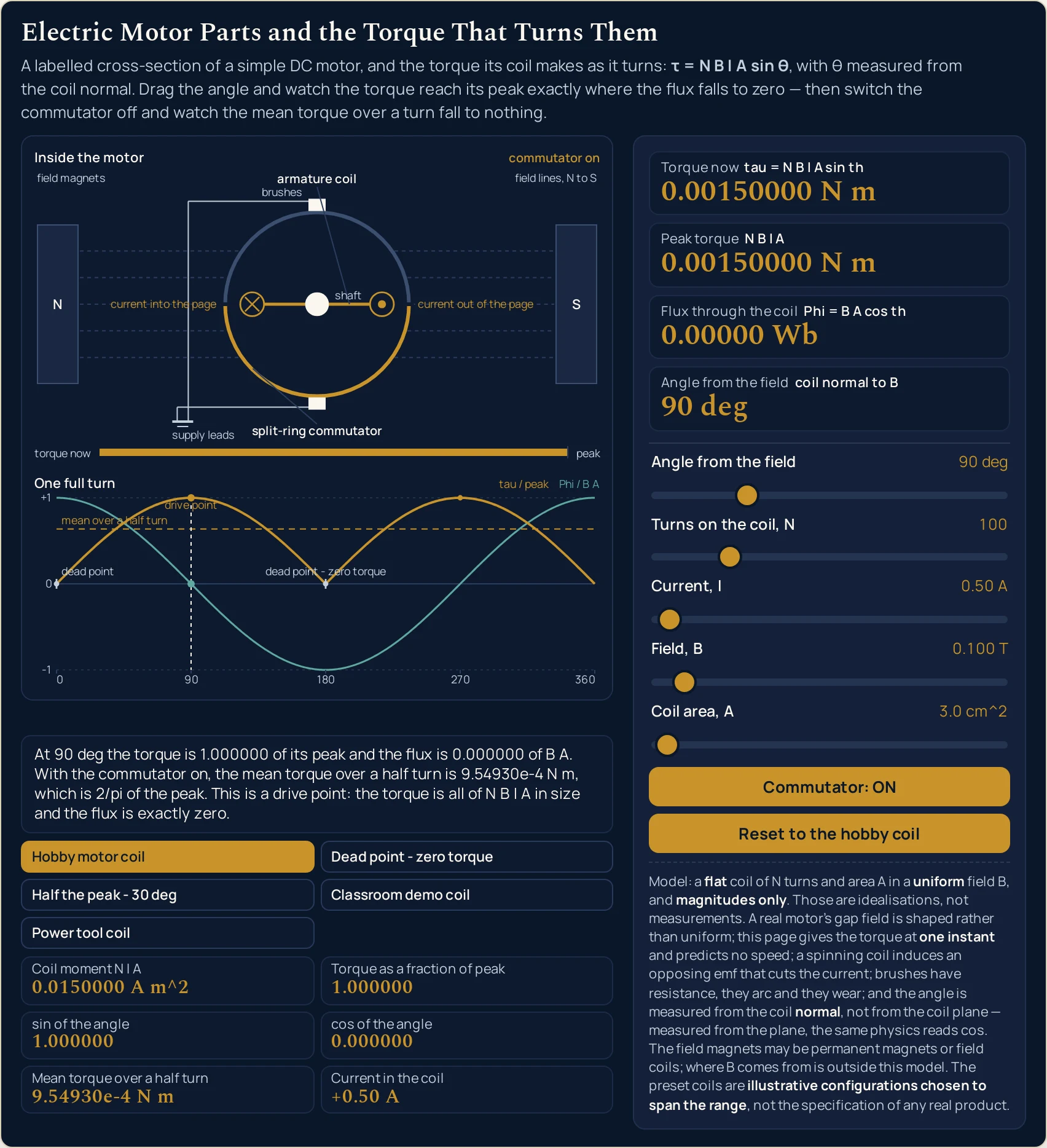
90 deg, which is a drive point. The torque card and the peak card read the same string, the flux card reads 0.00000 Wb, and the torque bar under the drawing is completely full. The band text here is what the drawing paints at this page’s own width; it shortens on a narrow column, band by band.Worked example: change one thing at a time
Nothing in the three tables below was worked out here. Each row is a state the lab was put into through its own controls and then read back from, cell by cell, so every string in them is the panel’s own. The first table moves the angle and holds the four coil sliders still.
One: the angle, with the coil left alone
The opening coil throughout, the commutator on, and only the first slider moving. Read the Peak torque column down before anything else: it is the same string ten times.
| Angle from the field | Torque now | Peak torque | Flux through the coil | Fraction of peak | Sine of the angle | Cosine of the angle | Current in the coil |
|---|---|---|---|---|---|---|---|
| 0 deg | 0.00000 N m | 0.00150000 N m | 3.00000e-5 Wb | 0.000000 | 0.000000 | 1.000000 | +0.50 A |
| 30 deg | 7.50000e-4 N m | 0.00150000 N m | 2.59808e-5 Wb | 0.500000 | 0.500000 | 0.866025 | +0.50 A |
| 45 deg | 0.00106066 N m | 0.00150000 N m | 2.12132e-5 Wb | 0.707107 | 0.707107 | 0.707107 | +0.50 A |
| 60 deg | 0.00129904 N m | 0.00150000 N m | 1.50000e-5 Wb | 0.866025 | 0.866025 | 0.500000 | +0.50 A |
| 89 deg | 0.00149977 N m | 0.00150000 N m | 5.23572e-7 Wb | 0.999848 | 0.999848 | 0.017452 | +0.50 A |
| 90 deg | 0.00150000 N m | 0.00150000 N m | 0.00000 Wb | 1.000000 | 1.000000 | 0.000000 | +0.50 A |
| 91 deg | 0.00149977 N m | 0.00150000 N m | -5.23572e-7 Wb | 0.999848 | 0.999848 | -0.017452 | +0.50 A |
| 180 deg | 0.00000 N m | 0.00150000 N m | -3.00000e-5 Wb | 0.000000 | 0.000000 | -1.000000 | +0.50 A |
| 270 deg | 0.00150000 N m | 0.00150000 N m | 0.00000 Wb | 1.000000 | -1.000000 | 0.000000 | -0.50 A |
| 360 deg | 0.00000 N m | 0.00150000 N m | 3.00000e-5 Wb | 0.000000 | 0.000000 | 1.000000 | +0.50 A |
The first and fourth columns are the whole lesson. Where the torque is nothing the flux is at its largest size, and where the torque is all of 0.00150000 N m the flux is 0.00000 Wb. The two cells after them say why in the plainest possible way: the sine and the cosine of one angle, printed side by side, and the torque follows the first while the flux follows the second.
The 89, 90 and 91 degree rows are there to show how flat the top is. A whole degree either side of the drive point still reads 0.00149977 N m, which is why a real machine is not fussy about sitting exactly on 90 degrees and is very fussy indeed about not stopping on 0. The flux, by contrast, has already changed sign between those two rows.
The last column is the commutator doing its job inside this table. It reads +0.50 A everywhere except the 270 degree row, where it is -0.50 A, because the current was reversed as the coil went through the dead point at 180. The torque at 270 is therefore 0.00150000 N m rather than a negative number, and the turning effect has stayed in one sense. The magnetic field guide is where the sideways push on the wire that does all this comes from.
Two: the commutator, with everything else held still
The same coil again, at four angles, with the switch on and then off. The two Mean torque columns are the argument; the rest is there so you can see that nothing else was touched.
| Angle from the field | Torque now, switch on | Torque now, switch off | Coil current, switch on | Coil current, switch off | Mean torque, switch on | Mean torque, switch off |
|---|---|---|---|---|---|---|
| 90 deg | 0.00150000 N m | 0.00150000 N m | +0.50 A | +0.50 A | 9.54930e-4 N m | 0.00000 N m |
| 180 deg | 0.00000 N m | 0.00000 N m | +0.50 A | +0.50 A | 9.54930e-4 N m | 0.00000 N m |
| 270 deg | 0.00150000 N m | -0.00150000 N m | -0.50 A | +0.50 A | 9.54930e-4 N m | 0.00000 N m |
| 359 deg | 2.61786e-5 N m | -2.61786e-5 N m | -0.50 A | +0.50 A | 9.54930e-4 N m | 0.00000 N m |
Read the two right-hand columns across, not down. With the switch on the coil averages 9.54930e-4 N m over a half turn at every one of these angles; with it off it averages 0.00000 N m over a full turn at all of them. The coil is identical in both cases, and so is the peak it could reach.
The 270 degree row is where the two sides visibly part company. On the left the current has been reversed and the torque is a positive 0.00150000 N m; on the right the current is still +0.50 A and the torque is -0.00150000 N m, the same size pushing the other way. Half a turn of that cancels the other half, which is exactly what the mean column reports.
The 180 degree row is the one to be careful with. Both sides read 0.00000 N m, so a reader glancing at that row alone would conclude the switch does nothing. It is the only angle in the table where the two sides agree on the instantaneous reading, and it is agreeing because the torque is zero either way — which is the dead point, not the commutator.
Three: the five preset coils
These are the presets at the values their own buttons write, with the five slider labels the panel prints beside them. The first three rows are one coil at three angles, which is why their peak column never changes.
| Preset | Turns | Current | Field | Coil area | Angle | Torque now | Peak torque | Flux through the coil | Mean over a half turn |
|---|---|---|---|---|---|---|---|---|---|
| Hobby motor coil | 100 | 0.50 A | 0.100 T | 3.0 cm^2 | 90 deg | 0.00150000 N m | 0.00150000 N m | 0.00000 Wb | 9.54930e-4 N m |
| Dead point - zero torque | 100 | 0.50 A | 0.100 T | 3.0 cm^2 | 0 deg | 0.00000 N m | 0.00150000 N m | 3.00000e-5 Wb | 9.54930e-4 N m |
| Half the peak - 30 deg | 100 | 0.50 A | 0.100 T | 3.0 cm^2 | 30 deg | 7.50000e-4 N m | 0.00150000 N m | 2.59808e-5 Wb | 9.54930e-4 N m |
| Classroom demo coil | 20 | 2.00 A | 0.050 T | 100.0 cm^2 | 60 deg | 0.0173205 N m | 0.0200000 N m | 2.50000e-4 Wb | 0.0127324 N m |
| Power tool coil | 50 | 15.00 A | 0.350 T | 12.0 cm^2 | 45 deg | 0.222739 N m | 0.315000 N m | 2.96985e-4 Wb | 0.200535 N m |
Rows one to three are one coil at three angles and nothing else changes. Four identical slider columns, an identical peak, an identical mean, and three different torques. Row three is the half-way case: 7.50000e-4 N m against a peak of 0.00150000 N m, so the printed torque is half the printed peak and the fraction cell reads 0.500000.
Rows four and five are there so the page is not about one coil. The classroom coil trades turns for area — 20 turns of 100.0 cm^2 — and the power tool coil trades both for current, 50 turns at 15.00 A in 0.350 T. Between them the torque column spans from thousandths of a newton metre to 0.222739 N m, and the newton metre is the same unit the torque guide uses for a force on a lever arm.
The last column is the only one that needs the commutator to mean anything. Every figure in it assumes the current is reversed each half turn; with the switch off, all five rows read 0.00000 N m instead. It is the one column in this table that is a property of the whole machine rather than of the coil at an instant.
Formula and symbol reference
The band at the head of this page carries both relations rather than the torque alone, because the dead point is unintelligible without the second one. Every reading on the panel is one of those two, a factor inside one of them, or a constant comparing the two.
The symbol column below uses the panel’s own names, spelled the way the lab’s own cards spell them in plain ASCII, with tau, Phi and th written out rather than drawn. Note the unit column on the area row in particular: the panel is labelled in square centimetres and the relation wants square metres, and those two differ by a ten-thousandth rather than a hundredth.
| Symbol or readout | Meaning | Unit | In this lab |
|---|---|---|---|
| th | The angle between the coil normal and the field. The normal is the line at right angles to the flat of the coil, so a coil lying along the field is at 90 degrees and one facing it square on is at 0 | degree (deg) | the first slider, 361 whole-degree positions from 0 deg to 360 deg, opening on 90 deg. It is the only control that moves the drawing: the coil turns, the split in the ring turns with it, the torque bar fills and empties, and the marker slides along the curve below. |
| N | Turns on the coil. Each turn carries the same current and contributes the same amount, which is why this factor multiplies the whole thing | a plain count | the second slider, 1 to 500 in steps of 1, opening on 100. Alone at its ends it takes the opening coil from 1.50000e-5 N m to 0.00750000 N m, with the other four sliders untouched. |
| I | Current through the coil. This is the quantity the commutator reverses, and the only one on the panel that is ever printed with a sign | ampere (A) | the third slider, 0.10 A to 20.00 A in steps of 0.05, opening on 0.50 A. Alone at its ends it gives 3.00000e-4 N m and 0.0600000 N m. The grid cell beside it prints the signed value, +0.50 A or -0.50 A. |
| B | The field in the gap the coil turns in. It is an input here rather than a prediction: where it comes from is outside this model | tesla (T) | the fourth slider, 0.005 T to 1.500 T in steps of 0.005, opening on 0.100 T. Alone at its ends it gives 7.50000e-5 N m and 0.0225000 N m. It scales the torque and the flux together, so the fraction of peak does not move with it. |
| A | The area enclosed by ONE turn of the coil, because the turns are already counted on their own slider. An area is a length squared, so its conversion runs twice as far as a length’s | square centimetre on the panel, square metre in the relation | the fifth slider, 0.5 cm^2 to 200.0 cm^2 in steps of 0.5, opening on 3.0 cm^2. Alone at its ends it gives 2.50000e-4 N m and 0.100000 N m. The SI value is the reading multiplied by 1e-4, not by 1e-2. |
| tau | The torque on the coil at the angle you have set, which is the whole point of the panel. It is an instant, not a motion | newton metre (N m) | the first card, at six significant figures, in exponential form below a thousandth. Over the five sliders together it runs from 2.50000e-8 N m with everything at its minimum to 300.000 N m with everything at its maximum — ten decades of torque on one panel. |
| peak | The largest torque this coil could make, which is the four factors multiplied with no sine in them. It describes the coil rather than its position | newton metre (N m) | the second card. It does not move when you drag the angle: at all ten angles in the first table below it holds 0.00150000 N m. Across the five presets it reads 0.00150000, 0.0200000 and 0.315000 N m. |
| Phi | The flux through that same coil at that same instant, carried here as the companion of the torque rather than as a subject of its own | weber (Wb) | the third card. On the opening coil it runs from 3.00000e-5 Wb at 0 deg through 0.00000 Wb at 90 deg to -3.00000e-5 Wb at 180 deg. Its largest size is B times A, which the angle cannot exceed. |
| mean | What the coil averages over a half turn with the current reversed each half turn — the number the commutator buys | newton metre (N m) | the grid cell labelled Mean torque over a half turn. On the opening coil it reads 9.54930e-4 N m with the switch on and 0.00000 N m with it off, and on the power tool coil 0.200535 N m against the same 0.00000 N m. |
| fraction of peak | How much of the coil’s own ceiling the current angle is delivering. It is computed from the angle, never by dividing the first card by the second | dimensionless | the grid cell labelled Torque as a fraction of peak, from 0.000000 at a dead point to 1.000000 at a drive point, reading 0.500000 at 30 deg and 0.707107 at 45 deg. The two cells beside it print the sine and the cosine separately. |
If you read one row twice, make it the second-to-last. The mean is the only reading on the panel that is a statement about a whole turn rather than about this instant, and it is the only one the commutator button can move without any slider moving. The grid cell beside it, Coil moment N I A, is why the turns, the current and the area never appear apart: change one of them and the panel has no way to tell which you changed.
The angle convention on the first row is worth checking against another tool before you quote anything. The magnetic flux calculator states the identical convention and returns the cosine half in webers, which is the same number this lab prints on its third card. If the two ever disagreed about what the angle means, one of them would be wrong by a complement.
The physics: why the torque dies twice every turn
The field pushes sideways on the current in each side of the coil. Those two pushes act on opposite sides of the shaft, so they turn the coil rather than move it along, and the area of the coil is what sets how far apart they act. Stack more turns and each adds the same amount, which is the N in the first card.
How much of that push does any turning depends on the angle, and that is the entire content of the sin th. At 90 deg all of it is working and the torque is the whole of N B I A. At 0 deg both forces lie along the one line joining the coil’s two sides, stretching it across its width with no lever arm about the shaft, so the torque is exactly nothing however large the current is.
The same angle read through a cosine instead gives the flux, which is why the third card is on the panel at all. Over all 361 whole degrees, the torque as a fraction of its peak squared plus the flux as a fraction of B times A squared comes to one, with a worst error of 2.220e-16 — so the two readings are genuinely two views of one angle. The magnetic flux guide is where the flux side is set out properly; this lab only borrows it.
There is a deeper way to say the same thing: the torque is the current multiplied by the rate at which the flux linkage changes with the angle, which the cluster reference script measures to 1.669e-9 over 35 angles. That is why the peak sits exactly where the flux crosses zero rather than anywhere near where the flux is large. A cosine changes fastest where it passes through nothing.
And that is the whole case for the commutator. A coil that reaches a dead point with its current unchanged has nothing to turn with, and over a full turn its average torque is zero — the reference script measures that signed mean at -4.981e-17. Reverse the current every half turn and the average becomes two over pi of the peak, 63.6620 per cent, which is the figure the mean cell carries and the only number on the panel that describes a whole turn.
Everything above is a size. Which way a given coil swings is a separate question with its own rule, and the guide to the direction rule is where it is settled; nothing on this panel answers it. Where the field itself comes from is outside the model too — it may be permanent magnets or field coils, and the electromagnet guide is where the second of those is built.
| Part of the drawing | What it paints | What it does not claim |
|---|---|---|
| the parts band | The upper band, titled Inside the motor. A cross-section with every part named in the drawing itself: field magnets with field lines, N to S crossing the gap, the armature coil seen edge-on at the angle you have set, the shaft, the split-ring commutator with the segment each brush touches shaded, the brushes and their supply leads. A torque bar runs along the foot of it, labelled torque now at one end and peak at the other |
it does not claim to be a particular machine, or to be drawn to any scale. The two conductors carry a dot and a cross labelled current out of the page and current into the page, which say what the current is doing in a drawn section and nothing about which way anything turns. The band’s own corner reads commutator on or commutator bypassed, and with the switch off the ring is still drawn rather than quietly removed |
| the turn band | The lower band, titled One full turn. Two normalised curves on ONE shared vertical scale from minus one to plus one, ticked 0, 90, 180, 270, 360 along the bottom, with a legend reading tau / peak and Phi / B A. A marker follows the angle slider, the dead points carry dead point - zero torque and the drive points drive point, and one horizontal line reads mean over a half turn |
it does not put the two curves on two different scales, which is the one way a picture like this can flatter itself. Both are divided by their own maximum and drawn against the same axis, so where the torque curve touches zero the flux curve is visibly at its extreme. With the commutator off the mean line drops onto zero and relabels itself mean over a full turn = 0 |
| the torque bar | The gauge across the foot of the upper band. Its filled length is the torque now as a share of the peak, so it is completely full at a drive point and completely empty at a dead point — the drawn length at 0 deg is nought pixels, not a short stub |
it is not a direction indicator and it is not a speedometer. It shows what share of this coil’s own ceiling the present angle is delivering, which is the same number the grid prints as the fraction of peak, and nothing about how fast anything is going or which way |
| what the picture is for | Watching one angle move two readings in opposite directions, and watching a single button change what a whole turn averages to without changing one coil value. Every string in both bands is also printed in the panel beside the drawing, so the picture can be checked against the readings instead of trusted | it is not a measurement of anything. Every pixel is arithmetic on five slider positions and one switch, so it shows the shape of one relation rather than an observation of a machine; the five preset coils are an illustrative choice spanning the range, and only the torque in each of them is computed |
The dead points print as a clean zero on purpose, and that is worth knowing before you quote anything else off this panel. Taken raw, binary arithmetic gives the sine of 180 degrees as 1.22465e-16 rather than nothing, which at six significant figures would reach the readout on the one state the page most wants clean. The angle is snapped on the whole degree before the sine is taken, and the reference script measures that the residue would otherwise show at exactly 2 of the 361 whole degrees.
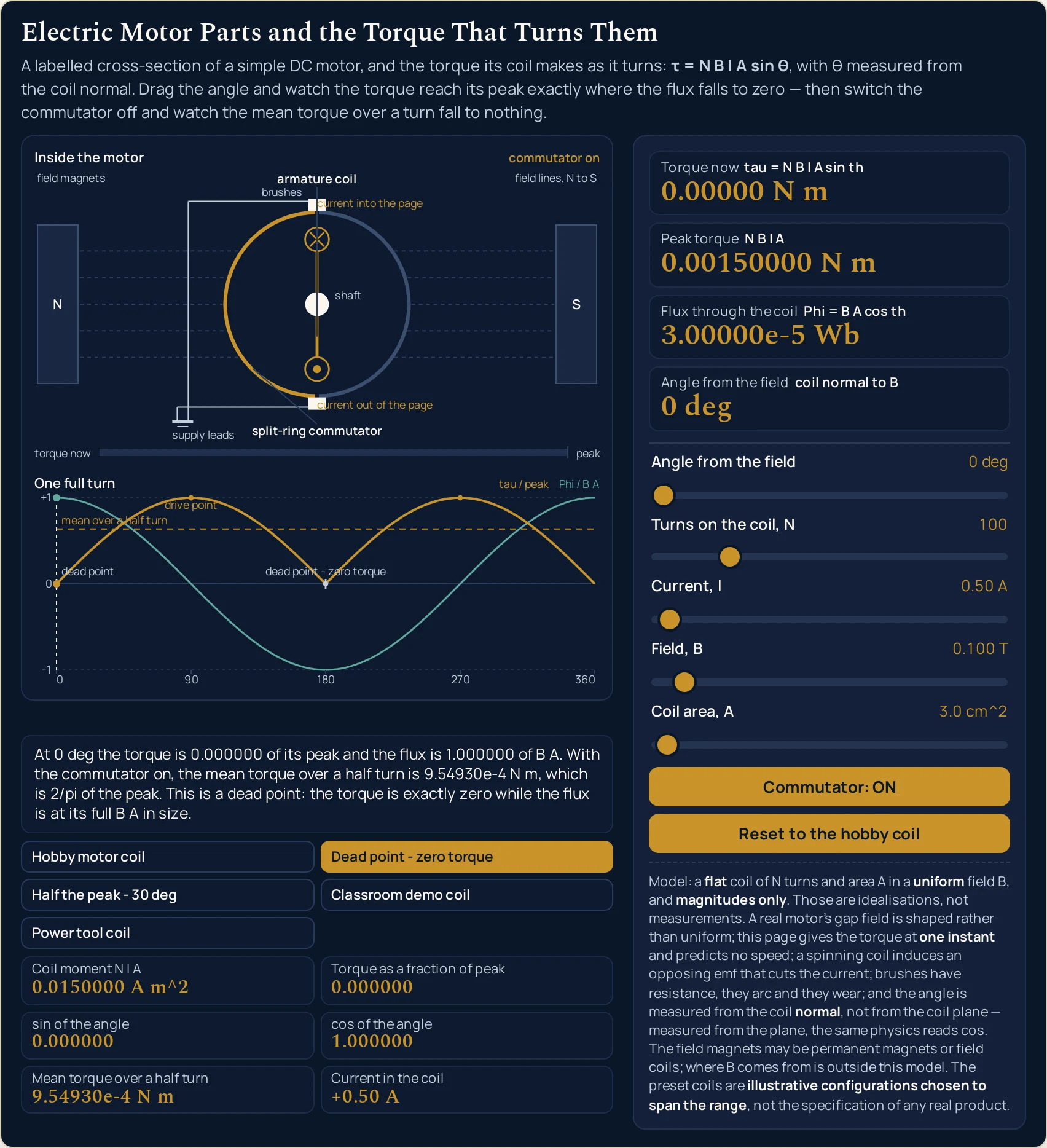
0.00000 N m while the flux card has risen to 3.00000e-5 Wb, and the torque bar at the foot of the upper band is drawn at nought length rather than as a short stub. In the lower band the marker sits where the torque curve touches zero and the flux curve is at its highest.Where the electric motor parts simulator breaks down
Every state the five sliders reach is answered, and the arithmetic is not where this panel can let you down. What it cannot do is be a real machine, and what it refuses to do is treat its own idealisations as facts. The first two items below matter more than the rest put together.
- The angle is measured from the coil normal, and that is the usual slip
- Read this one before any of the others. The normal is the line at right angles to the flat of the coil, and the fourth card says so in the words
coil normal to B. Take the angle to the coil’s face instead and you have its complement, which swaps the sine for the cosine: at30 degyou would be reading0.866025off the wrong cell and calling it the fraction of peak. The two cells are printed separately for exactly this reason. - A real gap field is not uniform, and a real coil is not flat
- The relation assumes the same field everywhere across a coil of no thickness. A real machine shapes the field in its gap so the turning effect stays near its peak through much of the turn, which is precisely what a flat uniform field cannot do, and the curve in the lower band is the textbook idealisation of that rather than any particular motor’s. Treat the shape as the argument and the numbers as illustrative.
- It is one instant, not a motion
- Every reading is the torque at the angle you have set. The panel has no revolution rate, no speed and no power, because turning a torque into a motion needs a load and a moment of inertia that appear nowhere here, and nothing on it may be read as a rating for a machine. The only reading that describes a whole turn is the mean cell, and even that is an average rather than a prediction of what any coil would actually do.
- A spinning coil fights itself
- A moving coil generates an emf of its own that opposes the supply and cuts the current actually flowing, so the current slider is not the constant this lab treats it as once a machine is really running. That effect belongs to the electromagnetic induction guide, and it is named here and developed nowhere.
- The commutator here is instantaneous, and the ring has two segments
- The switch flips the current with no gap, no resistance and no arc. Real brushes have all three and they wear, which is the whole reason brushless machines exist. The drawn ring is split into two segments, where a basic commutator uses three contact areas so the coil is never left sitting at a dead spot — the two-segment case is drawn here precisely because it is the one where the dead point is visible.
- A preset does not touch the switch
- This is a practical trap rather than a physical one. Pressing a preset writes the five coil values and nothing else, so if you have switched the commutator off and then start comparing presets, every mean cell you read will be
0.00000 N mand the lower band will keep its signed curve. Only Reset to the hobby coil restores the opening state with the switch on. - The sliders are motor-shaped, so two useful cases are off the ends
- The current control stops at
0.10 Aand the area control at200.0 cm^2, which is deliberate: these are the ranges a small motor lives in. A moving-coil instrument carrying a tenth of a milliampere and a coil of one whole square metre are both outside them and cannot be dialled in here at all. The motor torque calculator takes typed numbers with unit menus and carries both of those as presets. - Everything here is a size, never a sense
- The panel prints magnitudes, with one deliberate exception: the current cell carries a sign, because reversing the current is the commutator’s entire job and that reversal has to be visible. No reading anywhere says which way the coil swings, and the drawing’s dot and cross describe the current in a cross-section rather than a rule for the turn. The right-hand rule simulator is where that question is answered.
- The lab runs one way only, and measures nothing
- You set five numbers and a switch and it reports what they imply. There is no box to type a torque into, no unit menu, and no way to hand it a figure from a real machine. The five preset coils are illustrative configurations chosen to span the range rather than any product’s specification, no number here came from an instrument, and every digit is arithmetic on slider positions. Verify any figure against your own source before you use it.
Where the electric motor parts simulator is actually used
- Answering the question the parts list cannot: why is that part there
- This is what the panel exists for. Switch the commutator off, drag the angle through a full turn, and read the mean cell:
0.00000 N m, with every coil value untouched. Switch it on and the same cell reads9.54930e-4 N m. A list can tell you a motor has a split-ring commutator; this is the number that says what would happen without one. - Seeing where in the turn a coil has nothing to give
- Press Dead point - zero torque and the torque bar is empty while the flux card is at its largest. Nothing is broken: at that angle the forces have no leverage at all. It is the single fact a motor is designed around, and the lower band marks both of the angles where it happens, at
0and180degrees. - Getting a feel for how big a coil torque is before you quote one
- Five sliders over their whole range take the first card from
2.50000e-8 N mto300.000 N m, which is ten decades on one panel. A hobby-sized coil sits in the thousandths and a power tool coil in the tenths, so a figure in whole newton metres off a coil this size should make you check your area unit before you check anything else. - Checking an angle convention before you substitute into anything
- Load any preset and the sine and cosine cells are printed side by side for the same angle, so it takes one glance to see which one your source meant. A number taken to the coil’s face rather than its normal is out by a complement, and that error is invisible at
45 degand at its worst near the dead points. The magnetic flux simulator is the companion picture for the cosine half. - Separating what a coil could do from what it is doing
- The first two cards are that distinction on screen. Drag the angle and the first moves while the second does not; drag any of the other four sliders and both move together. That is the difference between a coil’s ceiling and its present position, and the fraction-of-peak cell is the ratio of the two computed from the angle rather than from the cards.
- Teaching the five parts with the names attached to the picture
- The upper band labels every piece in the drawing itself, so a class can be shown
split-ring commutatorandbrusheson the same screen as the number they change. Press the first two presets in turn and the argument is one screen long. The electromagnet simulator is the one to open next if the question becomes where the field itself comes from.
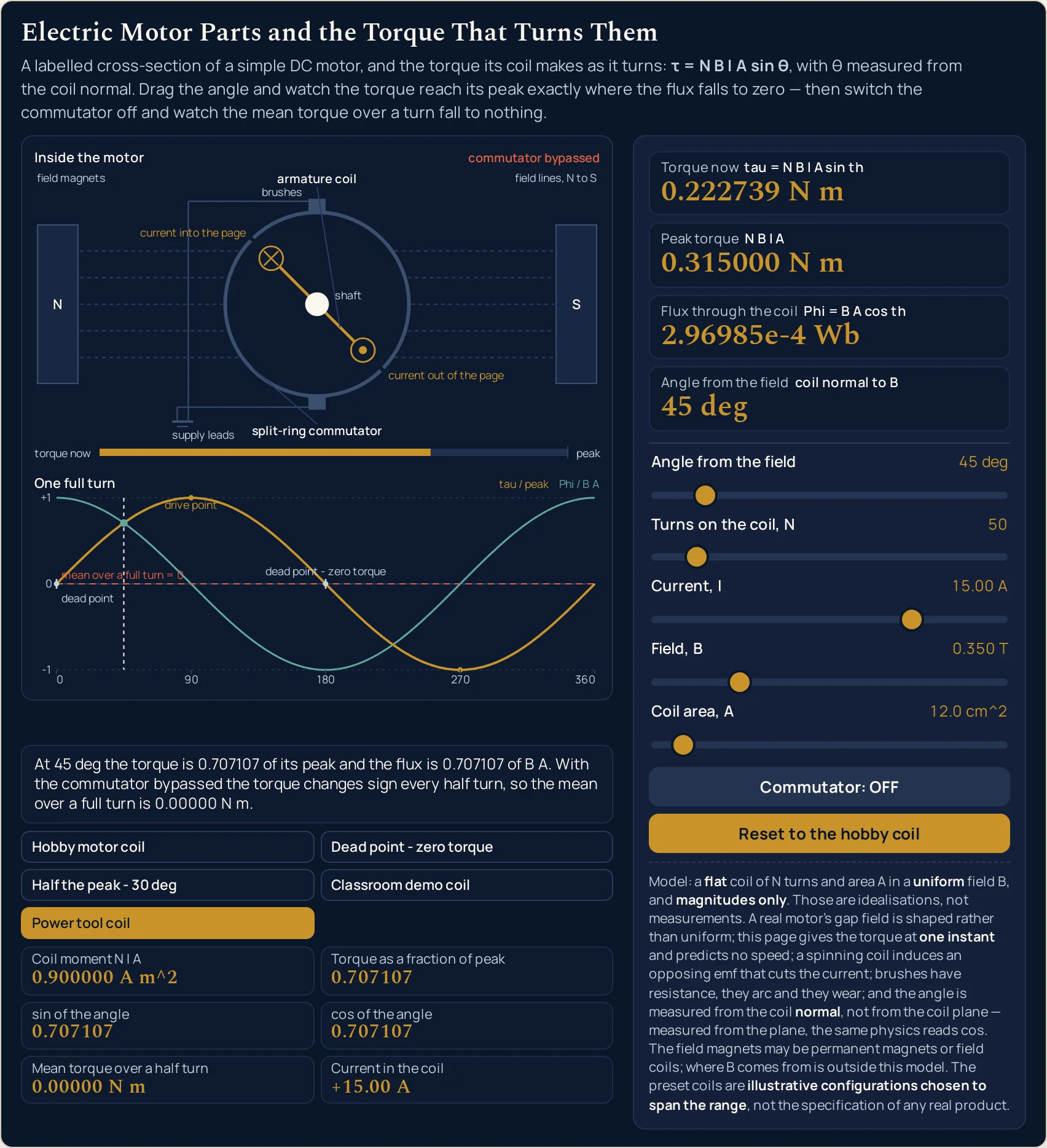
0.222739 N m against a peak of 0.315000 N m — but the mean cell has dropped to 0.00000 N m, the upper band labels itself commutator bypassed while still drawing the ring, and the lower band’s curve now spends half the turn below the axis.Where to go next
A panel can put you in a state and let you move one thing at a time, and that is the end of what a panel is for. The electric motor parts guide is where the subject is written out: the five parts, a reason for each one tied to a factor in the relation, why the turning effect dies twice a turn, and the problems worked step by step.
Four posts own the pieces this lab takes as given. The magnetic field guide is where the sideways force on a current-carrying wire comes from, the magnetic flux guide is the cosine companion of this lab’s sine, the electromagnet guide is where a field coil gets its field, and the torque guide is the newton metre with no magnetism in it at all.
Two more pick up what this lab names but does not develop. The guide to the direction rule is where which-way-it-turns is settled, and the electromagnetic induction guide is where the same machine run backwards becomes a generator.
On the tool side, the motor torque calculator takes typed figures and solves in five directions, the magnetic flux calculator runs the cosine half of the same angle, the torque calculator does the mechanical form with a force and a lever arm, and the Faraday’s law calculator turns a changing flux into an emf.
Three neighbouring pictures sit beside this one: the magnetic flux simulator, the electromagnet simulator and the torque simulator. Beyond them there is the simulation library, an index of calculators, and the blog for everything written out at length.
Frequently asked questions
Which angle does the slider mean, the coil or the line at right angles to it?
It is the angle to the coil normal, which is the line at right angles to the flat of the coil, and the fourth card says so beside its reading: coil normal to B. The magnetic flux calculator states the identical convention, so one angle serves both tools. The slider itself cannot be entered wrongly; the slip happens when a figure measured from the coil plane is carried across to it.
Why does the torque card read zero at the very angle where the flux card is largest?
Because the two readings are the same angle through different trig functions: the torque is the sine of it and the flux is the cosine. At 0 deg the torque card reads 0.00000 N m while the flux card reads 3.00000e-5 Wb, its largest for this coil. At 90 deg they have swapped: 0.00150000 N m and 0.00000 Wb.
What does the commutator button actually change?
It changes nothing about the coil and everything about the average. With it on, the mean cell on the opening coil reads 9.54930e-4 N m, which is 2/pi of the peak. Switch it off and that cell reads 0.00000 N m, because the torque then spends half of every turn with the opposite sign. The four coil sliders do not move.
Why does the current cell change sign on its own when I drag the angle?
Because that is the reversal the commutator exists to make, shown as a number. With the switch on, the cell reads +0.50 A on the opening coil and flips to -0.50 A once the angle passes a dead point, which is what keeps the turning effect in one sense. With the switch off it stays at +0.50 A all the way round.
Why does the peak card not move when I drag the angle?
Because the peak is N B I A with no sine in it, so it describes the coil rather than its position. Drag the angle from 0 deg to 360 deg on the opening coil and the peak card holds 0.00150000 N m at every one of the 361 positions, while the torque card runs from 0.00000 N m up to that same figure and back.
Does pressing a preset put the commutator back on?
No. A preset writes the five coil values and nothing else, so it leaves the switch exactly where you left it, and the mean cell will go on reading 0.00000 N m until you turn it back on. Only the Reset to the hobby coil button restores the whole opening state, the switch included. It is worth knowing before you compare two presets.
Why is the torque at thirty degrees printed as 7.50000e-4 rather than as a decimal?
Because the readouts carry six significant figures and switch to exponential form below a thousandth, and that choice is made from the printed value rather than from the number behind it. The same reading at 45 deg is inside the band and prints as 0.00106066 N m. Both are the same six figures; only the form differs.
Can I set the sliders to a moving-coil instrument or to a one square metre coil?
No, and that is deliberate: these sliders are motor-shaped. The current control stops at 0.10 A and the area control at 200.0 cm^2, so a tenth of a milliampere and a coil of one square metre are both outside them. The companion motor torque calculator takes typed numbers with unit menus and carries both of those cases as presets.
How many of the printed digits should I trust?
The torque, peak, mean and flux cards print six significant figures, the angle prints whole degrees, the sine and cosine cells six decimals and the current two. Those are display choices rather than claims about precision: the lab measures nothing and every digit is arithmetic on five slider positions. Verify any figure against your own source before you use it.
References & formula source
- Every figure on this page comes from one relation and one angle. A flat coil of N turns and area A carrying a current I, sitting in a uniform field B, feels a turning effect of N times B times I times A multiplied by the sine of the angle between the coil normal and the field. The flux through that same coil at that same instant is B times A multiplied by the cosine of the identical angle. The panel applies those two and multiplies out; the written guide derives them and works the problems.
- A university physics textbook chapter on the force and torque on a current loop, read on 14 November 2026, is the one external source behind this page. Four things are taken from it rather than paraphrased loosely: that motors are the most common application of magnetic force on current-carrying wires; that for a rectangular loop the net torque simplifies to the current times the area times the field times the sine of the angle; that the current is reversed by commutators and brushes, which press against the commutator to keep electrical contact as it spins; and that once the loop is aligned with the field the current is reversed so the turning effect continues.
- The same chapter gives the N-turn form of the coil quantity on its own page, and composing that with its single-loop torque is where this page gets its N. That is one step of substitution between two equations on one source page, not a new claim, and nothing here suggests the source omitted anything or got a sign wrong. The source carries the direction as well as the size; this lab works in sizes and says so, because which way a coil turns has its own rule and its own page on this site.
- That chapter also makes a design claim this lab can put a number on, and it is paraphrased here rather than quoted because the original sentence is awkward: a basic commutator uses three contact areas rather than two, so the coil is never left sitting at a dead spot where its instantaneous torque is zero. The arithmetic behind that is the cluster reference script: one coil falls to exactly nothing twice a turn, while three coils evenly spaced never drop below 86.6 per cent of the peak. The drawing on this page shows the two-segment case on purpose, because that is the one where the dead point is visible.
- The dead points are exact, and making them print exactly is a deliberate piece of arithmetic rather than luck. Taken raw, binary arithmetic gives the sine of 180 degrees as 1.22465e-16 and of 360 degrees as 2.44929e-16 rather than as nothing, which at six significant figures would print on the one state this lab most wants clean. The angle is therefore snapped on the whole degree before the sine is taken, and the reference script measures that the residue would otherwise reach the readout at exactly 2 of the 361 whole degrees. Zero degrees is not one of them: that one is exact already.
- The pairing the panel is built around was measured, not asserted. Over all 361 whole degrees, the torque as a fraction of its peak squared plus the flux as a fraction of B times A squared comes to one, with a worst error of 2.220e-16; the torque is largest at 90 degrees and the flux is exactly zero at 90 and 270 degrees, the same two angles. The deeper form, that the torque is the current multiplied by the rate at which the flux linkage changes with angle, agrees to 1.669e-9 over 35 angles with a central difference.
- The commutator reading is a constant, not an average of the drawn curve. With the current reversed every half turn the mean torque is two over pi of the peak, which is 0.6366197723675814 or 63.6620 per cent, and the grid cell is computed from that constant rather than by sampling the line above it. Without the reversal the mean over a full turn is zero, measured at -4.981e-17, which is why the mean cell reads a clean 0.00000 N m with the switch off. Simpson over 20,000 intervals agrees with two over pi to 4.185e-15.
- The simulation was gated before this page was written, and every table cell here was read back out of the running file rather than computed here. A reference oracle at 76 checks with none failing; a Node tier at 178 checks with none failing; a headless Chrome tier at 126 checks with none failing over five viewports and eight iframe columns down to 160 pixels wide; a mutation pass over 78 planted faults with 71 killed and all 7 survivors explained by an executed proof, 10 deliberately bad mutants rejected and the deliverable unchanged; a height pass at a measured maximum of 932 pixels against a 1000 pixel ceiling; and a cross-browser pass of 19 checks in which all 149 readouts came out identical in Chrome and in Firefox at each of four widths. The 52 harvested states were then replayed in a second engine and all 520 compared cells matched.
- What was not verified, stated as a gap rather than left to be assumed. Safari and WebKit: the build on the machine this was tested on cannot start, so Safari was never exercised and nothing on this page is evidence about it. Assistive technology: every slider carries a label and a live value text and the drawing carries a full description of both bands, but no screen reader was driven and no real touch target was pressed. And the webfonts as a reader gets them, since there are no system faces on the test machine and the exact pixel widths a reader sees were not measured.
- Nothing on this page is a measurement, and the five preset coils are illustrative configurations chosen to span the range rather than the specification of any product. A hobby motor coil might carry a hundred turns; this one does because that is what the button writes. Only the torque, the peak, the flux and the mean in each preset are computed. The model is one flat coil in a uniform field, in magnitudes, at a single instant, with a steady current and no losses, and every one of those words is an idealisation the panel prints in a fixed line under its own controls. Verify any figure against your own source before you use it for anything that matters.
- Further reading: Electric motor — Wikipedia