The RC time constant is the time taken for a capacitor in a resistor-capacitor circuit to charge to about 63.2% of its final voltage, or to fall to 36.8% of its starting voltage while discharging. It equals resistance multiplied by capacitance: tau equals R times C, measured in seconds.
Pull the plug on a desktop computer and watch the power LED. It does not snap off — it lingers, dims, then fades out over a second or so. Somewhere on that motherboard a capacitor is emptying itself through a resistor, and the pace of that fade is not random.
It is set by two numbers you could read off the components with a magnifying glass. Multiply them together and you get a time. That product is the RC time constant, and once you can calculate it you can predict how long almost any charging or discharging circuit will take to settle.
What Is the RC Time Constant?
The RC time constant is the characteristic timescale of a circuit containing resistance and capacitance, equal to the product of the two. It is written with the Greek letter tau (τ), and despite being built from an ohm and a farad, it comes out in seconds.
Think of filling a bucket through a narrow hose, where the tap pressure drops as the bucket fills. Early on, water pours in fast. As the level rises the flow eases off, so the last centimetre takes far longer than the first. A capacitor charges exactly like that — and τ is the natural yardstick for how sluggish the whole process is.
Here is the part that catches people out. One time constant is not the time to charge fully. It is the time to get 63.2% of the way there, and that figure is fixed by the mathematics, not by the components you picked.
Why 63.2%?
Because the charging curve is exponential. After one time constant the fraction of the journey still remaining is e-1, which is 0.368 — so the fraction completed is 1 – 0.368 = 0.632. Every RC circuit ever built hits that same 63.2% mark at t = τ, whether τ is a microsecond or an hour.
The RC Time Constant Formula
The RC time constant formula is τ = R × C: multiply the resistance in ohms by the capacitance in farads and the answer comes out directly in seconds.
Every symbol, with its SI unit:
| Symbol | Quantity | SI unit | Typical values |
|---|---|---|---|
| τ | Time constant | second (s) | 1 μs to 10 s |
| R | Resistance in series with the capacitor | ohm (Ω) | 100 Ω to 1 MΩ |
| C | Capacitance | farad (F) | 1 pF to 10 mF |
Why Ohms Times Farads Gives Seconds
This one is worth doing once, because it makes the formula impossible to forget. An ohm is a volt per amp, and a farad is a coulomb per volt.
Multiply them and the volts cancel: Ω × F = (V/A) × (C/V) = C/A. Since an amp is a coulomb per second, C/A is a coulomb divided by a coulomb-per-second — which is a second. The result is exact, not approximate, and it follows straight from the SI definitions of the derived units maintained by NIST.
In practice, the arithmetic is easiest if you convert everything to base units first: kilohms to ohms, microfarads to farads. A 47 kΩ resistor with a 22 μF capacitor gives τ = 47,000 × 0.000022 = 1.034 s. If you would rather skip the unit-juggling, our RC Time Constant Calculator handles the prefixes and will also rearrange the formula to solve for R or C when you already know the timing you need.
How the RC Time Constant Works
The exponential shape comes from a feedback loop hiding inside the circuit. Here is the circuit in question:
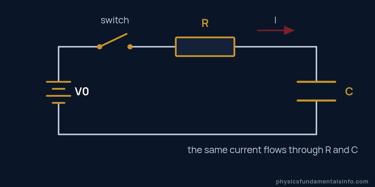
A series RC circuit. Closing the switch starts the charging process governed by τ = RC.
Close the switch and, for an instant, the capacitor is empty. The full supply voltage appears across the resistor, so the current is at its maximum, V0/R.
That current pushes charge onto the capacitor, and charge on a capacitor is voltage. As the capacitor voltage climbs, less of the supply is left over for the resistor — so the current falls. Less current means slower charging, which means the voltage climbs more gently still.
The circuit throttles itself. That is the signature of exponential behaviour: the rate of change is proportional to how far you still have to go.
The Derivation in Three Lines
Apply the loop rule around the circuit. The supply voltage is shared between the resistor and the capacitor:
Current is the rate at which charge arrives, I = dQ/dt, so this becomes a differential equation in Q alone:
Separating variables and integrating gives the charging solution. The group RC sits in the exponent, which is precisely why it has the units of time:
For a capacitor already charged to V0 and then discharged through R, the same algebra with the supply removed gives the mirror-image curve:
MIT’s introductory circuits course treats these as the standard first-order system response, which is the general name for any system whose behaviour is governed by a single time constant like this one.
The 63% Rule and What Happens After 5 Time Constants
A capacitor reaches 63.2% of its final voltage after one time constant, 86.5% after two, and 99.3% after five — at which point engineers call it fully charged. The curve never mathematically reaches 100%, so “fully charged” is always a practical judgement rather than an exact moment.
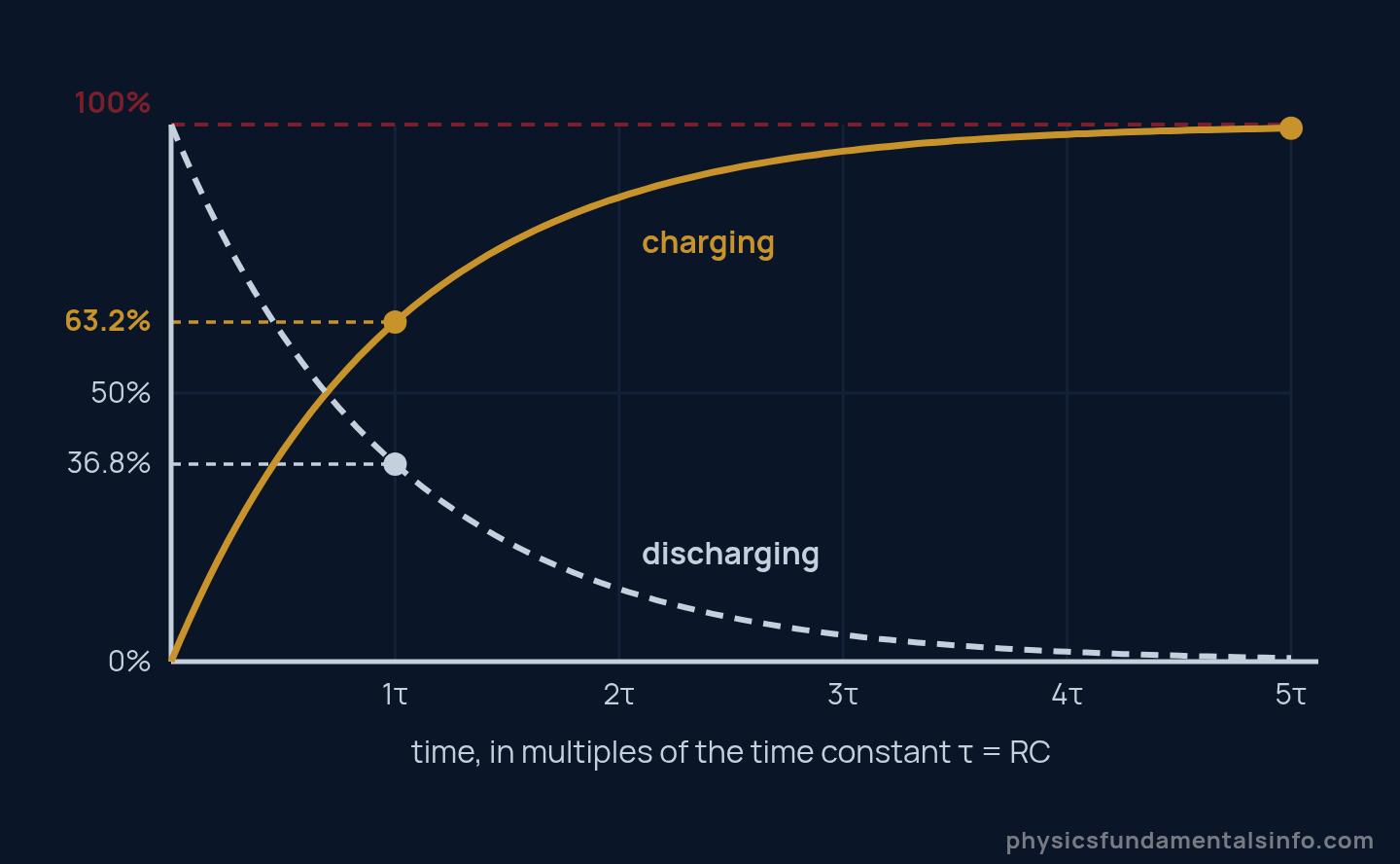
Charging and discharging curves for an RC circuit. Both cross the 63.2% and 36.8% marks at exactly one time constant.
The percentages below are universal. They do not depend on the supply voltage, the resistor, or the capacitor — only on how many time constants have elapsed.
| Time elapsed | Charged to | Discharged to | What it means in practice |
|---|---|---|---|
| 1τ | 63.2% | 36.8% | The defining point of the time constant |
| 2τ | 86.5% | 13.5% | Usable for rough logic-level switching |
| 3τ | 95.0% | 5.0% | Within 5% — acceptable for many timers |
| 4τ | 98.2% | 1.8% | Better than most component tolerances |
| 5τ | 99.3% | 0.7% | Treated as fully charged or fully discharged |
Five Shortcuts Worth Memorising
Once you know τ, these five relationships let you answer most exam and bench questions without touching a calculator:
- The 63% point. At t = τ the capacitor is 63.2% charged, or has 36.8% of its charge left when discharging.
- The 5τ rule. After five time constants the circuit has settled to within 0.7%. Call it done.
- The half-time. Voltage halves every 0.693τ, because ln 2 = 0.693. Handy for reading an oscilloscope trace.
- The 10-90% rise time. Going from 10% to 90% takes 2.2τ, since ln 9 = 2.197. This is the figure datasheets quote.
- The corner frequency. Treat the same circuit as a filter and its -3 dB point sits at f = 1/(2πτ).
Real-World Examples of the RC Time Constant
RC time constants set the pace of an enormous range of everyday electronics, from millisecond switch debouncing to the multi-second charge-up of a camera flash. The same τ = RC governs all of them; only the size of R and C changes.
1. Camera Flash
A flash unit uses two wildly different time constants in the same circuit. A large resistance charges the storage capacitor slowly over a second or two — that is the rising whine you hear on older cameras.
Firing the flash then dumps that charge through a xenon tube whose resistance is tiny, so the discharge τ collapses to under a millisecond. Same capacitor, two time constants differing by a factor of a thousand.
2. Switch Debouncing
Mechanical switch contacts bounce for a few milliseconds when they close, generating a burst of false pulses. Placing an RC network with τ of roughly 10 ms across the switch smooths the bouncing into a single clean edge, because the capacitor simply cannot change voltage fast enough to follow the chatter.
3. Audio Tone Controls and Filters
The treble roll-off in a guitar amplifier is an RC circuit chosen so its corner frequency lands where the designer wants the tone to soften. A 1 kΩ resistor with a 100 nF capacitor gives τ = 100 μs, which puts the -3 dB point at about 1.59 kHz.
4. Windscreen Wiper Delay
Intermittent wiper settings are often nothing more cunning than a capacitor charging through a variable resistor. Turning the delay knob changes R, which changes τ, which changes how long the capacitor takes to reach the threshold voltage that triggers the next sweep.
5. Power Supply Bleed Resistors
Large smoothing capacitors in mains equipment can hold a lethal charge long after the plug is pulled. Designers deliberately fit a high-value bleed resistor across them so that τ is a few seconds and the capacitor self-discharges to a safe level within 5τ — which is exactly why the safety label tells you to wait before opening the case.
Common Misconceptions About the RC Time Constant
Misconception 1: A Higher Voltage Charges the Capacitor Faster
It does not change the timing at all. Look at the formula — V0 appears nowhere in τ = RC.
Doubling the supply doubles the final voltage and doubles the initial current, and those two effects cancel exactly. A 12 V supply and a 3 V supply reach their own 63.2% marks at precisely the same instant. The curve gets taller, never faster.
Misconception 2: The Capacitor Is Fully Charged After One Time Constant
After 1τ the capacitor is only 63.2% charged, with more than a third of the journey still to go. This is easily the most common slip in exam papers.
Worse, the remaining 36.8% takes four more time constants to close down to 0.7%. If a question asks for “fully charged”, the expected answer is almost always 5τ.
Misconception 3: A Bigger Capacitor Charges More Quickly
Larger capacitance means a longer time constant, not a shorter one. A bigger capacitor is a bigger bucket — it needs more charge to reach the same voltage, so with the same resistor limiting the flow it takes proportionally longer.
The same logic applies to resistance. A bigger R restricts the current more, so τ rises. Both quantities push the timing in the same direction, which is why they simply multiply.
Misconception 4: R Is Always the Resistor You Can See
The R in τ = RC is the Thévenin resistance the capacitor sees when you look back into the rest of the circuit, not necessarily one labelled component.
If a 10 kΩ resistor feeds the capacitor and a second 10 kΩ resistor sits in parallel with it, the capacitor sees the two in parallel — 5 kΩ — and τ halves accordingly. Students who grab the nearest resistor value here get an answer that is out by a factor of two. Worked Problem 7 below walks through exactly this case.
How the RC Time Constant Relates to Other Circuit Ideas
The RC time constant sits at the junction of several ideas you have probably already met, and it is much easier to remember once you see how they connect.
Its two ingredients come straight from circuit fundamentals: electrical resistance controls how fast charge can flow, while capacitance sets how much charge is needed to raise the voltage by one volt. The derivation itself leans on Ohm’s law for the resistor and on the definition of electric current as the rate of charge flow.
The exponential itself is not unique to circuits. A discharging capacitor and a decaying radioactive sample obey mathematically identical laws, which is why the RC half-time of 0.693τ mirrors the half-life of an unstable nucleus. Anything whose rate of decrease is proportional to what remains produces this same curve.
Finally, working out the effective R often means combining resistors first, so the rules for series and parallel circuits are a prerequisite for anything beyond a textbook single-resistor case.
A Sanity Check on Energy
Here is a result that surprises most first-year students. Charging a capacitor through a resistor from a fixed supply always wastes exactly half the energy the battery delivers, no matter what resistance you choose.
The battery supplies CV02, the capacitor stores ½CV02, and the resistor dissipates the other ½CV02 as heat. Using a smaller resistor makes the charging faster but not more efficient — it just burns the same energy in less time.
Worked Problems
Show Solution
Solution:
Step 1: Use the definition of the time constant, τ = R × C.
Step 2: Convert to base SI units. R = 10 kΩ = 10 × 10^3 Ω, and C = 100 μF = 100 × 10^-6 F.
Step 3: Multiply. τ = (10 × 10^3) × (100 × 10^-6) = 1.0 s.
Answer: τ = 1.0 s
Show Solution
Solution:
Step 1: Use the charging equation V(t) = V0(1 – e^(-t/τ)) with t = τ.
Step 2: At t = τ the exponent is -1, so e^(-1) = 0.3679.
Step 3: V = 5.0 × (1 – 0.3679) = 5.0 × 0.6321 = 3.16 V.
Answer: V = 3.16 V, which is 63.2% of 5.0 V
Show Solution
Solution:
Step 1: Find the time constant. τ = 47 × 10^3 × 22 × 10^-6 = 1.034 s.
Step 2: Find how many time constants have elapsed. t/τ = 2.0 / 1.034 = 1.934.
Step 3: Apply the charging equation. e^(-1.934) = 0.1445, so V = 9.0 × (1 – 0.1445) = 9.0 × 0.8555.
Answer: V = 7.70 V (about 86% charged, consistent with just under 2τ)
Show Solution
Solution:
Step 1: Find the time constant. τ = 4.7 × 10^3 × 330 × 10^-6 = 1.551 s.
Step 2: Use the discharge equation V = V0e^(-t/τ) and rearrange for t: t = τ × ln(V0/V).
Step 3: Substitute. V0/V = 12/3.0 = 4.0, and ln 4.0 = 1.386, so t = 1.551 × 1.386 = 2.150 s.
Answer: t = 2.15 s
Show Solution
Solution:
Step 1: Set the charging equation to 99%. 1 – e^(-t/τ) = 0.99, so e^(-t/τ) = 0.01.
Step 2: Take natural logs. t/τ = ln(100) = 4.605, so τ = 0.020 / 4.605 = 4.343 × 10^-3 s.
Step 3: Rearrange τ = RC for C. C = τ/R = (4.343 × 10^-3) / (1.0 × 10^3) = 4.343 × 10^-6 F.
Answer: C = 4.34 μF, so a standard 4.7 μF capacitor would be the practical choice
Show Solution
Solution:
Step 1: Relate half-time to the time constant. Setting V/V0 = 0.5 in V = V0e^(-t/τ) gives t½ = τ × ln 2.
Step 2: Rearrange for τ. τ = t½ / ln 2 = 0.035 / 0.6931 = 0.05049 s = 50.5 ms.
Step 3: Rearrange τ = RC for R. R = τ/C = 0.05049 / (10 × 10^-6) = 5049 Ω.
Answer: τ = 50.5 ms and R = 5.05 kΩ (about 5.0 kΩ)
Show Solution
Solution:
Step 1: Find the Thévenin resistance seen by the capacitor. Looking back from the capacitor, the supply becomes a short circuit, so the two resistors appear in parallel.
Step 2: Combine them. R = (10 × 10)/(10 + 10) = 5.0 kΩ, so τ = 5.0 × 10^3 × 100 × 10^-6 = 0.50 s.
Step 3: Find the final voltage. Once charging stops no current flows into the capacitor, so the resistors act as a simple divider: V = 10 × 10/(10 + 10) = 5.0 V.
Answer: τ = 0.50 s and the capacitor settles at 5.0 V, not 10 V
Show Solution
Solution:
Step 1: Find the time constant. τ = 1.0 × 10^3 × 100 × 10^-9 = 1.0 × 10^-4 s = 100 μs.
Step 2: Use the relationship between the time constant and the corner frequency, f = 1/(2πτ).
Step 3: Substitute. f = 1 / (2π × 1.0 × 10^-4) = 1 / (6.283 × 10^-4) = 1592 Hz.
Answer: τ = 100 μs and the cutoff frequency is 1.59 kHz