The flow rate formula simulator is a free interactive lab built around the quantity that refuses to move. Set the inlet bore and the inlet mean speed — between them they fix the rate — then drag the downstream bore and watch the rate card hold one string while the speed card sweeps across two orders of magnitude. The pipe steps abruptly rather than tapering, the rate is labelled once on an arrow spanning the step, and no pressure is computed anywhere on this page.
Flow Rate Formula
The flow rate is the area times the mean speed: Q = A v, with A = pi d^2 / 4 for a round pipe. The inlet bore and the inlet mean speed are what set the rate; change the downstream bore and the rate card refuses to move while the speed card jumps, exactly reciprocally. The tracer marks are released at equal intervals, so the same volume of fluid passes between any two of them - which is why their gaps stretch where the flow runs faster. Their drift is slowed to read. No pressure is computed anywhere on this page.
Load a real flow rate
The first seven buttons are the lab’s own presets, pressed by id and nothing else. The last four press one of those and then move a slider or two, which is what anyone does half a minute in. Taken in order they tell a story: one rate through three different downstream bores, then the bores made equal, then a change of fluid, then a change of vessel, and finally the two ends of what the sliders can reach.
Pick a pipe above, or drag the four sliders yourself.
What Is the Flow Rate Formula Simulator?
The flow rate formula simulator is a free interactive physics lab that runs in your browser, with nothing to install and no sign-up. It draws a round pipe in side elevation which steps abruptly from one bore to another at mid-length, carries one steady rate through both sections, and labels that rate once, on a gold arrow spanning the step. The placement is the claim: the rate is the quantity that does not change where the bore does.
Four sliders drive it. Inlet diameter d1 and Downstream diameter d2 both run 10 to 500 mm in whole millimetres, Inlet mean speed v1 runs 0.10 to 8.00 m/s in steps of 0.05, and Vessel to fill V runs 1 to 1000 L in whole litres. Four buttons pick the fluid — Water, Air, Glycerine and SAE 30 oil — four more pick the unit the rate is printed in, seven presets load a published state, and Pause flow and Reset finish the panel.
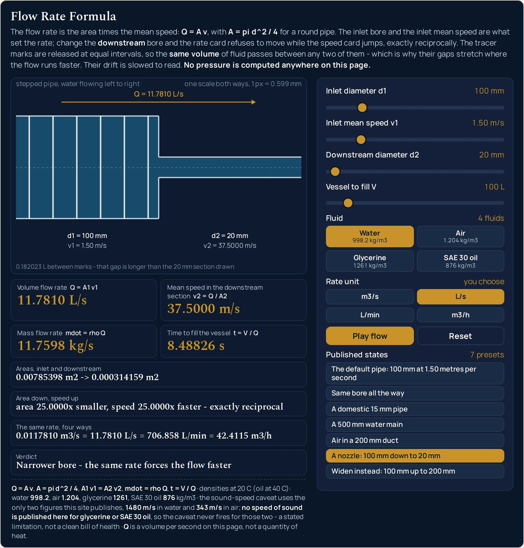
Eight readouts answer. Four cards give Volume flow rate, Mean speed in the downstream section, Mass flow rate and Time to fill the vessel; a compact grid beneath them adds Areas, inlet and downstream, Area down, speed up, The same rate, four ways and a Verdict. On the state the lab opens in they read 11.7810 L/s, 6.00000 m/s, 11.7598 kg/s, 8.48826 s and Narrower bore - the same rate forces the flow faster.
Each of the three cards beside the rate answers to exactly one control that moves nothing else. Drag the downstream bore and the speed card sweeps while the rate card holds one string; press a fluid button and only the mass flow moves; drag the vessel and only the fill time moves. The rate itself answers to the inlet bore and the inlet speed, because those two are what set it.
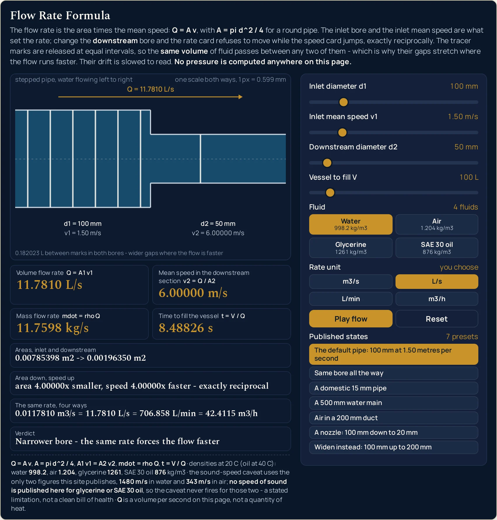
The ratio row states the reciprocity rather than implying it: at the opening state it reads area 4.00000x smaller, speed 4.00000x faster - exactly reciprocal, and one factor is worked out once and printed twice, so the two figures cannot drift apart. Press Same bore all the way and that row reads same area, same speed while the drawing becomes a single uniform pipe with no step in it at all.
The tracer marks are released at equal intervals, so the same volume of fluid passes between any two of them — which makes their gaps wider in whichever section the flow is faster, never narrower. The caption under the drawing gives that volume in litres on every frame, and it also names the one scale the picture is drawn to, because that scale moves with the larger of the two bores.
What the panel will not do, it says. Q = A v is kinematics, so no pressure, no pressure drop and no pumping power is worked out anywhere here, and extreme slider positions reach speeds no real pipe could sustain: the verdict then reads Past the speed of sound in water - the incompressible rule has gone, or the same sentence naming air. Those are the only two fluids this site publishes a speed of sound for, so glycerine and SAE 30 oil never trigger that caveat — a stated gap rather than a clean bill of health.
| Control | Range | Step, default and the card it moves |
|---|---|---|
| Inlet bore d1 | 10 to 500 mm | step 1; opens at 100; sets the rate with the inlet speed |
| Inlet mean speed v1 | 0.10 to 8.00 m/s | step 0.05; opens at 1.50; sets the rate with the inlet bore |
| Downstream bore d2 | 10 to 500 mm | step 1; opens at 50; moves the speed card and never the rate card |
| Vessel to fill V | 1 to 1000 L | step 1; opens at 100; moves the fill-time card alone |
| Buttons | 4 fluids, 4 units, 7 presets | one press each; the fluid moves the mass flow alone, plus Pause flow and Reset |
How to use the flow rate formula simulator
- Read the four cards before you touch anything. They are already answering: Volume flow rate 11.7810 L/s, Mean speed in the downstream section 6.00000 m/s, Mass flow rate 11.7598 kg/s and Time to fill the vessel 8.48826 s. Each card carries the closed form it comes from on its own label, so none of them is a mystery.
- Find the rate in the drawing before you change it. The gold arrow spans the step and carries Q = 11.7810 L/s once, which is the claim: the rate is what does not change where the bore does. Either side of it the pipe is labelled d1 = 100 mm with v1 = 1.50 m/s, and d2 = 50 mm with v2 = 6.00000 m/s.
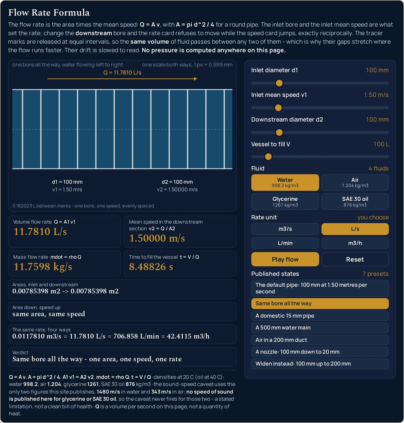
- Now move Downstream diameter d2 and watch only two things. The speed card sweeps and the rate card does not: at 20 mm it reads 37.5000 m/s, at 200 mm it reads 0.375000 m/s, and 11.7810 L/s stays on screen throughout. That one slider is the whole argument of the page.
- Drag it until the two bores match. At 100 mm the step disappears from the drawing entirely, the speed card reads 1.50000 m/s — the inlet speed, exactly — and the verdict reads Same bore all the way - one area, one speed, one rate. A lab that drew a step of zero height here would be drawing something that is not there.
- Press a fluid button and watch three cards ignore you. Glycerine takes the mass card to 14.8558 kg/s and SAE 30 oil takes it to 10.3201 kg/s, while the rate, the speed and the fill time keep the strings they had. Volume conservation does not know what the fluid is made of; kilograms per second do.
- Drag Vessel to fill V and watch the other three ignore you in turn. It moves the fill card alone. That is why the card is not the rate restated: it goes down as the rate goes up, and up as the vessel grows, and the two directions are easy to confuse until you have seen them.
- Choose the unit the rate is printed in — the lab will not choose for you. The four buttons give 0.0117810 m3/s, 11.7810 L/s, 706.858 L/min and 42.4115 m3/h for one pipe. That is deliberate: an automatic switch would add a rounding boundary for no gain, whereas four buttons make the conversion something you perform.
- Read the compact grid as a decomposition, not as more evidence. Areas, inlet and downstream shows the two areas the cards were built from, Area down, speed up prints the trade as one factor used twice, and The same rate, four ways is the whole unit ladder at once. The last of those restates the rate card on purpose, and its label says so.
- Use Pause flow when you want to look rather than watch. It stops the tracer marks where they are and leaves a clean static frame, which is the right state for reading the gaps between them. Press it again to resume; the drift is deliberately slowed to be read and is not a real-time speed.
- Reset is the way back when too many controls have moved to remember. It returns all four sliders, the fluid and the rate unit to their opening values and lights the first preset again. Touching any slider by hand drops the preset highlight, so no button can claim a state the cards do not show.
Dragging is the right way to see which card answers to which control, and a poor way to hit an exact figure. When you already have two of the three quantities and want the third typed out, the flow rate formula calculator solves the same relation for whichever one is missing, with unit menus on every box. For the definition itself, the full unit table and the worked problems, read the guide to the flow rate formula.
Worked example: change one thing at a time
Nothing in the four tables below was worked out here. Each row is a state the lab was put into on this page and then read back from, cell by cell, so every string in them is the panel’s own. The first table holds the inlet still and changes the downstream bore, then makes the bores equal, then changes the fluid.
| What was pressed | Downstream bore | Volume flow rate | Mean speed in the downstream section | Mass flow rate | Verdict |
|---|---|---|---|---|---|
| The default pipe: 100 mm at 1.50 metres per second | 50 mm | 11.7810 L/s | 6.00000 m/s | 11.7598 kg/s | Narrower bore - the same rate forces the flow faster |
| A nozzle: 100 mm down to 20 mm | 20 mm | 11.7810 L/s | 37.5000 m/s | 11.7598 kg/s | Narrower bore - the same rate forces the flow faster |
| Widen instead: 100 mm up to 200 mm | 200 mm | 11.7810 L/s | 0.375000 m/s | 11.7598 kg/s | Wider bore - the same rate lets the flow slow down |
| Same bore all the way | 100 mm | 11.7810 L/s | 1.50000 m/s | 11.7598 kg/s | Same bore all the way - one area, one speed, one rate |
| Air in a 200 mm duct | 200 mm | 157.080 L/s | 5.00000 m/s | 0.189124 kg/s | Same bore all the way - one area, one speed, one rate |
Rows one to three share every control but one, and that is the argument. Same inlet bore, same inlet speed, same fluid, same vessel — and one rate string, 11.7810 L/s, repeated down the column while the speed beside it goes from 6.00000 m/s to 37.5000 m/s to 0.375000 m/s. A hundredfold spread in one card and not a digit moved in the other.
Row four is the row worth pressing yourself. With the bores equal the downstream speed is the inlet speed to six figures, the drawing loses its step, and the verdict changes its wording rather than its arithmetic. It is the state that proves the speed card is reporting a consequence of the bore and not a second opinion about the rate.
Row five changes the fluid and the rate column barely notices. The duct carries 157.080 L/s — more than thirteen times the default pipe — and only 0.189124 kg/s of air with it. Anything metered, charged or burned by mass needs that second figure, and the fluid buttons are the only control that moves it.
The ratio row, and why it is one number printed twice
The Area down, speed up row is where the panel states the reciprocity instead of leaving you to spot it. The factor is worked out once from the two bores and then printed on both halves of the sentence, so the two figures are byte-identical by construction rather than by luck. The hydraulic cylinder force calculator uses the same squared-diameter step on a piston, if you want to see the area arithmetic on its own.
| What was pressed | Areas, inlet and downstream | Area down, speed up |
|---|---|---|
| The default pipe: 100 mm at 1.50 metres per second | 0.00785398 m2 -> 0.00196350 m2 | area 4.00000x smaller, speed 4.00000x faster - exactly reciprocal |
| A nozzle: 100 mm down to 20 mm | 0.00785398 m2 -> 0.000314159 m2 | area 25.0000x smaller, speed 25.0000x faster - exactly reciprocal |
| Widen instead: 100 mm up to 200 mm | 0.00785398 m2 -> 0.0314159 m2 | area 4.00000x larger, speed 4.00000x slower - exactly reciprocal |
| Same bore all the way | 0.00785398 m2 -> 0.00785398 m2 | same area, same speed |
Halving the bore is the trap this row exists for. From 100 mm to 50 mm the area does not halve, it quarters, and the row says area 4.00000x smaller, speed 4.00000x faster. Take the bore down to a fifth, 100 mm to 20 mm, and the factor is 25.0000x: the square in the area does all the work, and most wrong answers in this topic come from forgetting it.
The fill card, and the two rungs it climbs on its own
The fourth card divides the vessel by the rate, and its unit changes as the figure crosses sixty — decided on the rounded six-figure reading rather than on the raw float, so the value is never rounded twice. Rows two and three below are the same pipe with a different vessel, which is the cleanest way to see that only this card is listening.
| What was pressed or dialled | Vessel | Volume flow rate | Time to fill the vessel |
|---|---|---|---|
| A 500 mm water main | 1000 L | 392.699 L/s | 2.54648 s |
| A domestic 15 mm pipe | 10 L | 0.176715 L/s | 56.5884 s |
| The same 15 mm pipe, a bigger vessel | 100 L | 0.176715 L/s | 9.43140 min |
| Every slider at its floor | 1000 L | 0.00785398 L/s | 35.3678 h |
One rate, four buttons
The rate unit is yours to choose, and the ladder row underneath is unmoved by the choice. Press each button in turn at the opening state and the card walks the third column of this table while the fourth stays exactly where it was, because that row is the whole ladder every time. A pump quoted in cubic metres per hour and a meter reading in litres per second are the same pipe, and this is the thirty-second check that says so.
| Button | What the rate card prints | What the ladder row prints |
|---|---|---|
| m3/s | 0.0117810 m3/s | 0.0117810 m3/s = 11.7810 L/s = 706.858 L/min = 42.4115 m3/h |
| L/s | 11.7810 L/s | 0.0117810 m3/s = 11.7810 L/s = 706.858 L/min = 42.4115 m3/h |
| L/min | 706.858 L/min | 0.0117810 m3/s = 11.7810 L/s = 706.858 L/min = 42.4115 m3/h |
| m3/h | 42.4115 m3/h | 0.0117810 m3/s = 11.7810 L/s = 706.858 L/min = 42.4115 m3/h |
Formula and symbol reference
The lab prints its five relations on itself, in a fixed line under the drawing: Q = A v, A = pi d^2 / 4, A1 v1 = A2 v2, mdot = rho Q and t = V / Q. The first two are the definition and the geometry; the third is the same definition written at two stations; the last two are readings that follow without new physics.
One warning about the letter before the table. Q here is a volume per second, in cubic metres per second, and the same letter stands for a quantity of heat in watts in Fourier's law of heat conduction. Same symbol, different quantity, and nothing on this panel is an energy. The density that turns the rate into kilograms is the subject of the density formula guide.
Ten rows follow and only four of them are things you drag. Two are readings with no control at all, one is pressed on a button, and the last is a factor the panel works out for itself. For the sliders the right-hand column gives the end stops and the step; for everything else it gives the strings the lab prints and the range it prints them over.
| Symbol | Meaning | SI unit | In this lab |
|---|---|---|---|
| Q | Volume flow rate — the area times the mean speed, and the first card. It is a volume per second on this page | cubic metre per second | six significant figures in whichever unit you pressed: 0.0117810 m3/s, 11.7810 L/s, 706.858 L/min, 42.4115 m3/h. Across the sliders the rate runs from 0.00785398 L/s to 1570.80 L/s. |
| A1, A2 | The two cross-sectional areas, each formed from its own bore as A = pi d^2 / 4. Neither has a control of its own |
square metre | the grid row prints both at once: 0.00785398 m2 -> 0.00196350 m2 at the opening state, and 0.0000785398 m2 at a 10 mm bore, which is the smallest area the panel can draw. |
| d1, d2 | The two internal diameters, in whole millimetres. The inlet one helps set the rate; the downstream one cannot touch it | metre, set in millimetres | 10 to 500 mm each, in steps of 1; they open at 100 mm and 50 mm. Every published diameter is a whole number, so the thumb reaches each of them exactly. |
| v1 | Inlet mean speed, the second slider. With the inlet bore it is what sets the rate, and it is a mean across the section | metre per second | 0.10 to 8.00 m/s, in steps of 0.05, echoed beside the slider as 1.50 m/s, 1.00 m/s, 0.10 m/s. Every published speed is a multiple of the step. |
| v2 | Mean speed in the downstream section, the second card. This is the reading the downstream bore moves, and it moves nothing else | metre per second | six significant figures: 1.50000 m/s when the two bores match, 6.00000 m/s at the opening step, 37.5000 m/s through the 20 mm nozzle and 0.375000 m/s when the pipe widens to 200 mm. |
| mdot | Mass flow rate, the third card: the density times the rate. It is proportional to the rate at a fixed fluid, which the card says rather than hides | kilogram per second | six significant figures: 11.7598 kg/s for water at the opening rate, 14.8558 kg/s for glycerine and 10.3201 kg/s for SAE 30 oil at that same rate. |
| rho | Fluid density — pressed on a button rather than typed, because the four figures are the ones this site already publishes | kilogram per cubic metre | four fixed values, shown on the buttons themselves: water 998.2, air 1.204, glycerine 1261 and SAE 30 oil 876 kg/m3. |
| V | The vessel the fourth slider fills. It appears in no other reading on the panel | cubic metre, set in litres | 1 to 1000 L, in steps of 1, echoed as 10 L, 100 L, 1000 L. It is the only control that moves the fill card and the only one the other three cards ignore. |
| t | Time to fill the vessel, the fourth card, as t = V / Q. It falls as the rate rises, which is why it is not the rate restated |
second | the unit climbs on its own, on the rounded figure: 2.54648 s down a 500 mm main, 8.48826 s at the opening state, 9.43140 min for a hundred litres through a 15 mm pipe, 35.3678 h with every slider at its floor. |
| k | The area ratio on the Area down, speed up row — worked out once from the two bores and printed on both halves of that sentence |
dimensionless | not a control and not a card. 4.00000 at the opening step, 25.0000 through the nozzle, and the row drops the factor altogether for same area, same speed when the two bores are equal. |
If you read one row twice, make it k. It is the only entry with no control and no card, and it is what keeps the ratio row from being the speed card restated: one factor, two halves of a sentence, and a claim of exact reciprocity that the panel is in a position to make.
The physics: one rate, every bore
The rate is the area times the mean speed, and that is a definition rather than a law. In one second a steady flow sweeps a cylinder of fluid past any fixed section, as wide as the pipe and as long as the distance travelled in that second. Put a step in the pipe and nothing can accumulate at it, so the volume arriving each second is the volume leaving each second.
That is the whole of continuity, and the panel is built so you can watch it rather than take it on trust. From the test harness rather than a card: the downstream slider was swept across all 491 of its whole-millimetre positions and the rate card printed one single string, 11.7810 L/s, at every one of them, while the speed card printed 491 different ones. The rate does not depend on the downstream bore to a tolerance; it does not depend on it at all.
The speed, though, must. If the rate is fixed and the area falls, the speed has to rise by exactly the factor the area fell by, which is why the ratio row prints one number twice. And because the area goes as the square of the diameter, a bore halved is an area quartered: the speed-up is the square of the diameter ratio, not the ratio itself.
The v in all of this is the mean speed across the section, which matters the moment you compare it with anything measured. A real pipe has faster fluid in the middle than at the wall, and the Reynolds number guide is where that distinction, and the character of the flow it belongs to, is set out properly. This panel takes the mean as given and discusses no profile.
Four cards, four different functions of the controls, and the panel is deliberately arranged so that each of the three beside the rate answers to exactly one control that moves nothing else. The downstream bore moves the speed, the fluid buttons move the mass flow, the vessel moves the fill time, and the inlet pair move all four because they are what set the rate. One correspondence is stated rather than hidden: the mass flow is the density times the rate, so at a fixed fluid the two are proportional.
That correspondence is worth one more sentence, because it is the only pair on the panel that could be mistaken for a repeated reading. The ratio of the mass card to the rate card is the density, and from the test harness rather than a card: the four buttons sweep it from 1.204 to 1261, a span of more than a thousandfold. Two cards whose digits are unrelated, carrying different units, with one printing kilograms and the other litres.
What none of it says is what the flow costs. Q = A v is kinematics: it counts volume past a point and is silent about the pressure, the viscosity and the energy needed to push it there, which is why this lab computes no pressure anywhere. Bernoulli's principle is where the pressure side of a moving fluid lives, and the pressure-at-a-throat lab is its panel — a smooth venturi taper read for its pressure drop, where this one is an abrupt step read for its rate.
Where the flow rate formula breaks down
The arithmetic here is exact to the last digit a double can hold, and the panel will answer every position its sliders can reach. What fails is the physics around the edges of that bargain: a relation that counts volume and not cost, a density assumed constant, a mean read as a maximum, and one drawing asked to show two bores at once.
- It is kinematics, so some reachable states are arithmetically exact and physically absurd
- Nothing on this panel asks what drives the flow, so the sliders can reach a downstream speed that no pump, pipe or duct could sustain. The verdict card refuses to leave that unremarked: push the speed past the figure this site publishes for the fluid and it stops describing the bores and reads Past the speed of sound in air - the incompressible rule has gone, or the same sentence naming water. Treat that string as the panel declining to vouch for the state, not as a result.
- One rate at every station is the incompressible statement, and a gas only borrows it
- Volume in equals volume out exactly when the density does not change along the pipe. For a liquid that is close enough to exact for any practical bore; for a gas it holds while the pressure and temperature barely move, which in practice means well below the speed of sound. Above that, the volume arriving and the volume leaving are simply different numbers and nothing on this panel applies — including the mass card, which is the one reading that would survive the change if the density were tracked.
- Two of the four fluids carry no sound-speed caveat at all, and that is a gap in the warning
- This site publishes a speed of sound for water, 1480 m/s, and for air, 343 m/s. It publishes none for glycerine and none for SAE 30 oil, so the verdict can never fire for either of those two, however extreme the bores you set. Inventing a figure to close the gap was refused on purpose; the honest reading of a silent verdict on glycerine is that the threshold is unknown here, not that there is not one.
- Every speed on the panel is a mean, and a real section has no single speed
- Fluid at the wall moves slower than fluid in the middle, so both the slider and the card are averages across the section rather than anything a probe would read at one point. Feeding a centreline reading into the inlet slider will overstate the rate. The Reynolds number guide is where mean and local speeds are separated, and its lab is where the character of the flow gets a panel of its own.
- Where a viscosity and a pressure drop set the rate, a different relation fixes it
- In a long narrow tube under a steady pressure difference it is the viscosity that decides how much flows, and the relation that gives the rate there is Poiseuille’s law. The definition does not stop holding there — it will describe that flow perfectly well once a speed exists to put into it — but it has no way of producing the speed in the first place, and this panel carries no viscosity control and no pressure difference to give it one. The viscosity guide names that law and works it; this page does neither.
- At a large area ratio one scale cannot show both gaps, and the caption says which
- The marks are spaced by equal volume, so the gap in the faster bore is longer by the full area ratio. Past about six to one that gap is longer than the section drawn, and the caption changes from wider gaps where the flow is faster to naming the bore whose gap no longer fits. Drawing the marks closer together there instead would be a second scale, and this picture never has one.
- The drawing is to scale in the bores, and the smallest ones hit a floor
- Both sections are drawn to one scale set by the larger of the two, so a 10 mm bore beside a 500 mm one is a hairline by rights. It is drawn at a two-pixel minimum instead, because a line of zero width is not a pipe, and that is the one place the picture is generous rather than faithful. The cards and the area row are unaffected; read them, not the thickness.
- A fill time assumes a rate that never changes
- The fourth card divides the vessel by whatever rate is on screen and then holds that rate fixed for the whole of the fill. That is exact arithmetic about a flow nobody actually gets: the conditions driving a real fill drift while it is happening, and they drift in the direction that makes it take longer rather than shorter. Read the card as a lower bound on the time, not as a prediction of it, and the reference notes at the foot of this page say which three effects do the lengthening.
- Both bores are internal diameters, and the panel cannot tell when they are not
- A nominal pipe size is a label and an outside diameter includes the wall, and because the area follows the square, a bore five per cent out puts the rate about ten per cent out. The error lands in the answer rather than in the input you can see. Take the bore from the pipe schedule you are actually buying, and nothing here is a round section’s substitute for a rectangular duct or a part-full pipe — the Manning equation calculator is the open-channel tool.
- Two engines agree readout for readout, and Safari was never run at all
- From the cross-browser gate rather than a card: 174 readout values were put side by side in Chrome and in Firefox over five slider positions at each of four viewport widths, and every one matched. There is a hole in that, and it is Safari: the WebKit build on this box refuses to start without privileges the harness does not hold, so Safari was never exercised and nothing here is evidence about it. If your browser ever prints a figure this page does not, trust the panel in front of you and tell us.
Where the flow rate formula is actually used
- Settling the halve-the-bore argument in two button presses
- This is the misconception the lab exists for. Press The default pipe: 100 mm at 1.50 metres per second and then A nozzle: 100 mm down to 20 mm: the rate card never changes its string while the speed card goes from 6.00000 m/s to 37.5000 m/s. Two presses, ten seconds, and the square in the area stops being something to remember and becomes something you watched.
- Sizing a domestic pipe against a main, on the same pair of axes
- Press A domestic 15 mm pipe and then A 500 mm water main: 0.176715 L/s against 392.699 L/s. The bore grew by a factor of about 33 and the speed only doubled, yet the rate grew by more than two thousandfold. That is the shape of every pipe-sizing conversation, and it is why a bore is chosen before a speed is argued about.
- Estimating a fill or a drain before anyone orders a pump
- The fill card answers the question most people actually arrive with. A hundred litres through the default pipe is gone in 8.48826 s; the same hundred litres through the 15 mm kitchen pipe takes 9.43140 min; a thousand litres through a 10 mm bore at a crawl takes 35.3678 h. Those are floors on the time, and they are usually enough to settle whether a plan is sensible.
- Working in kilograms when what is paid for is mass
- Press Air in a 200 mm duct: 157.080 L/s of air, and 0.189124 kg/s of it. Then press The default pipe, carrying glycerine and watch the mass card alone move to 14.8558 kg/s. Combustion air, refrigerant charges and anything sold by the tonne are specified in the second column, and only the fluid buttons touch it. The density calculator is where a density comes from if the fluid is not one of these four.
- Reading a rate in the unit the invoice is written in
- A pump is sold in litres per minute or cubic metres per hour, a meter reads in litres per second, and a textbook works in cubic metres per second. The ladder row puts one rate in all four at once, 0.0117810 m3/s = 11.7810 L/s = 706.858 L/min = 42.4115 m3/h, which is the quickest way to catch the factor-of-sixty slip that this topic is famous for.
- Choosing a nozzle, or deliberately choosing not to
- Narrowing the exit is how a jet is made: the same 11.7810 L/s leaves a 20 mm nozzle at 37.5000 m/s. Widening does the opposite, and Widen instead: 100 mm up to 200 mm drops the same rate to 0.375000 m/s, which is what a settling tank or an intake screen is for. One slider, two pieces of design intent, and no new physics between them.
- Getting the mean speed a flow-regime question needs before it can start
- Almost every next question about a pipe — laminar or turbulent, what the pressure drop will be, whether a probe is reading the right thing — wants a mean speed first. This panel is the quickest way to turn a bore and a rate into one. The Bernoulli equation calculator is where that speed becomes a pressure, and the guide to pressure in physics is the other thing a cross-section does.
Where to go next
A panel can show you which readings a control is allowed to move, and that is the end of what a panel is for. Flow Rate Formula (Q = Av) is where the subject itself is written out: what the rate is, the unit table in full, the area step, the mass flow rate, the fill time and the problems worked through from their own figures. The calculator that takes those figures typed heads the list of related tools below.
Three neighbouring subjects are deliberately absent from this panel, and each is written up on its own terms. Bernoulli's principle is where the pressure side of the story lives, the Reynolds number guide is where the mean speed meets laminar and turbulent flow, and the viscosity guide is where a pressure drop and a viscosity set the rate instead.
Further out, the density formula guide is where the mass card gets its density, the guide to pressure in physics and the Pascal law and hydraulics guide are the other two things an area does, and Fourier's law is where the other Q lives. Beyond that there is the whole simulation library to work through, an index of calculators for when typing beats dragging, and the blog for everything written out at length.
Frequently asked questions
Why does the rate card not move when I drag the downstream diameter?
Because the rate is set at the inlet, and the inlet has not changed. Volume cannot pile up at a step, so whatever arrives each second has to leave each second: the card holds one string, 11.7810 L/s, across the whole of that slider. The speed card is what absorbs the change instead, and it does so exactly reciprocally.
Why do the tracer marks spread apart in the narrower pipe instead of bunching up?
Because they are released at equal time intervals, so the gap between two of them is the local speed times that interval. Multiply a gap by the area it sits in and you get the same volume in both sections, which is the point of the whole page. Equal volume per gap forces the longer gap where the flow is faster, and the caption prints that volume in litres.
Why is there no pressure readout anywhere on this panel?
Because Q = A v is kinematics. It counts the volume crossing a section each second and says nothing about what pushes it, so a pressure card here would be an answer the arithmetic cannot give. The boundary is deliberate rather than an omission, and the fixed line under the drawing states it: no pressure is computed anywhere on this page.
Why does the verdict warn about the speed of sound in water and air but never in glycerine or oil?
Because this site publishes a speed of sound for water and air only, 1480 m/s and 343 m/s, and inventing a figure for the other two fluids would be worse than leaving the gap visible. So the caveat can fire on water and on air and never on glycerine or SAE 30 oil. Read that silence as missing data, not as a clean bill of health.
Why do I have to choose the rate unit myself instead of the lab switching it?
Because an automatic switch would add a rounding boundary and teach nothing. Four buttons make the same rate in four units something you do rather than something you watch: one press moves the card between 0.0117810 m3/s, 11.7810 L/s, 706.858 L/min and 42.4115 m3/h. The ladder row underneath prints all four at once and never changes when you press one.
The fill time changed from seconds to minutes. Which figure should I trust?
Both, because it is one time printed in two units. That card changes rung on the rounded six-figure reading rather than on the raw one, then prints six figures of the converted value: a hundred litres through the 15 mm pipe reads 9.43140 min rather than a rounded number of seconds. Drop every slider to its floor and it climbs again, to 35.3678 h.
What is the caption reading one scale both ways telling me?
That the bores and the length of the pipe are drawn to a single scale, and what one pixel of the picture is worth in millimetres. That scale is set by the larger of the two bores, so it moves as you drag, and the caption is reprinted on every frame. Without it a 10 mm pipe and a 500 mm pipe would look identical on screen.
What does exactly reciprocal mean on the Area down, speed up row?
That the two factors in that sentence are one number used twice. The area falls by some factor and the speed rises by the same factor, because their product is the rate and the rate has not moved. The lab works that factor out once and prints it on both halves of the row, so the two figures cannot drift apart in their sixth digit.
References & formula source
- Every figure on this panel comes out of four slider positions, two button rows and five closed forms, and nothing is fitted or measured. The lab prints all five on itself, in a fixed line under the drawing: the rate is the area times the mean speed, the area of a round bore is pi times the diameter squared over four, the rate is the same at every station so area times speed is too, the mass flow rate is the density times the rate, and the time to pass a volume is that volume divided by the rate.
- The four densities are not this cluster's own. They are taken verbatim from the fluid table this site already publishes on its Reynolds number tools - water 998.2, air 1.204, glycerine 1261 and SAE 30 oil 876 kilograms per cubic metre, at 20 degrees Celsius and the oil at 40 - so this lab agrees with its neighbours rather than introducing a second set of figures for the same four fluids.
- The sound-speed caveat uses only the two speeds this site already publishes, 1480 metres per second in water and 343 in air. No speed of sound is published here for glycerine or for SAE 30 oil, so the caveat can never fire for either of those two fluids. That is a stated gap in the warning rather than a statement that those two fluids are safe, and inventing a figure to close it would have been worse than leaving it open.
- This panel computes no pressure, no pressure drop, no head loss, no pumping power, no viscosity, no Reynolds number and no friction factor, and there is no card for any of them. That is not an omission: the relation it is built on counts volume past a section and is silent about what drives it, so the panel can reach states that are arithmetically exact and physically unavailable. The verdict card says so when the downstream speed passes the speed of sound in the fluid.
- The drift of the tracer marks is slowed so that it can be read, and the lab says so in its own opening line. Their spacing is the honest part: marks are released at equal intervals, so the volume between two of them is the same in both bores, and that is asserted against the drawn positions rather than claimed. Nothing about the speed of the animation on screen is a statement about how fast the fluid is moving.
- Each fill time is exact arithmetic about a rate that never changes. A real tank fills against a rising head, a real pump rides up its own curve and a real valve gets throttled, so treat the card as the floor on the time rather than the time. The same applies to every bore on the sliders: these are internal diameters, and a nominal pipe size or an outside diameter is a different number.
- Two engines were compared readout by readout rather than assumed to agree: this cluster's cross-browser gate put 174 readout values side by side in Chrome and in Firefox over five slider positions at each of four viewport widths, and every one matched. There is a hole in that, and it is Safari - the WebKit build on this box cannot launch, so Safari was never exercised here and nothing on this page is evidence about it.
- Every readout figure quoted on this page is a string this simulation printed for the button or the slider position named beside it, read back out of the running lab in a browser rather than worked out by hand. Each is computed from the exact value and rounded once, so re-deriving one printed figure from another will not always reproduce the sixth digit; the few figures here that are harness measurements rather than cards say so in their own sentences. Where a figure here and the lab part company, believe the lab, and verify anything you rely on before using it.
- Further reading: Volumetric flow rate — Wikipedia