Lenz's law settles the one thing Faraday's law leaves open: not how many volts, but which way round the loop they drive. An induced current always takes the direction whose own field works against the change of flux that made it, and that is exactly what the minus sign in ε = -N dΦ/dt records. This lab lets you move a magnet past a coil and watch that single rule decide four readings at once — the sign of the EMF, the sense of the current, the pole the coil presents to the magnet, and which way the force points. Every figure it prints is a figure for a point-dipole model, and none of them is a measurement.
Lenz's Law: Which Way Does the Current Go?
Slide the magnet along the axis of the coil: the flux through the coil changes, so a current is induced — and it always runs the way that fights the change, which is the minus sign in emf = -N dPhi/dt. Read the induced EMF with its sign, which way the current runs seen from the right-hand end of the axis, the pole the coil turns towards the magnet, and the force, which never helps the motion. A magnet held still induces nothing, however strong it is.
Induced current-26.98 mA
Flux per turn22.479 µWbflux through one turn
Flux linkage4.4959 mWbflux linkage, N times the flux
Slope of the linkage0.2698 Wb/mhow fast the linkage changes with position
Power dissipated7.28 mWheat in the circuit
Where the EMF peaks± 10.0 mmwhere the EMF peaks: half a coil radius
What Lenz's law says hereThe flux through the coil points right and is growing as the magnet moves in. The induced current runs clockwise seen from the right, turning the coil's near face into a north pole that repels the magnet.
Energy checkMechanical power in: 7.28 mW. Electrical power out: 7.28 mW. Lenz's law is energy conservation.
What to noticeThis is the peak: the EMF is largest at half a coil radius from the centre, not at the centre itself.
The model: a point dipole of 1.00 A·m2 on the axis of a coil of radius 20.0 mm with coincident turns, in a circuit of pure resistance — no self-inductance, and no figure here is a measurement. The force arrow is not drawn to scale: its length is on a square-root scale, because the force spans seven decades across these sliders. The motion arrow is proportional to the speed.
Induced EMF emf = -N dPhi/dt
-269.75 mV
induced EMF, sign and all
Which way the current runs
clockwise, seen from the right
which way the induced current runs
The coil's near face
the coil's near face is a north pole
the face the magnet is nearest
Force on the magnet F = m I dG/dz
7.28 mN
it repels the magnet, slowing the approach
Magnet position-10 mm
0 mm is the coil's centre; its radius is 20.0 mm
Magnet velocity1.0 m/s
positive is to the right; 0.0 m/s induces nothing
Turns on the coil200 turns
Circuit resistance10.0 Ω
The magnet itself
the magnet's north end points right
Load a case
custom setting
Tip: load a case, then press Flip twice — every sign reverses and comes back, and the force never moves.
Load a real case
The first five presets press the lab's own case buttons, which set the magnet's position, its velocity and which end points right, then name the case on the line beneath them. The last three write the four sliders directly, so that line stays at custom setting. Because the polarity is not a slider, those three leave the magnet pointing whichever way you last left it; their captions assume the north end is to the right, which is where Reset puts it.
Pick a case above, or drag the sliders yourself.
What Is the Lenz's Law Simulator?
The Lenz’s law simulator is a free interactive physics lab that runs in your browser — nothing to install and no sign-up. Put the magnet anywhere from -60 to +60 mm along the coil’s axis in 5 mm steps, set its velocity between -1.5 and +1.5 m/s, wind 50 to 300 turns and load the circuit with 1.0 to 20.0 Ω. The panel answers with the induced EMF and its sign, which way the induced current runs seen from the right-hand end of the axis, which pole the coil turns towards the magnet, and the force on the magnet — which always opposes the motion, whichever way it is going.
| Control | Range | Step |
|---|---|---|
| Magnet position | -60 to +60 mm | 5 mm |
| Magnet velocity | -1.5 to +1.5 m/s | 0.1 m/s |
| Turns on the coil | 50 to 300 turns | 10 turns |
| Circuit resistance | 1.0 to 20.0 Ω | 0.5 Ω |
| The magnet itself | north or south end right | Flip button |
How to use the Lenz's law simulator
- Load a case. The five buttons under Load a case — North pole pushed in, North pole pulled out, South pole pushed in, At the coil centre and Magnet held still — set the position, the velocity and the polarity together, and print the name on the case line. Touch any slider, or press Flip, and that line reverts to custom setting. Reset returns to -10 mm, +1.0 m/s, 200 turns, 10.0 Ω and the north end pointing right.
- Put the magnet somewhere. Magnet position runs from -60 to +60 mm in 5 mm steps, and the figure beside it reads back as “-10 mm”. Negative is to the left of the coil, 0 mm is its centre. The gold ring labelled now on the chart slides to the matching point on the EMF curve, between the two dotted verticals labelled peak.
- Set how fast, and which way. Magnet velocity covers -1.5 to +1.5 m/s in steps of 0.1, positive to the right. This is the control that makes everything happen: Induced EMF, Which way the current runs, The coil's near face and Force on the magnet all answer to it, and at “0.0 m/s” all four go to nothing at once. The motion arrow on the bench is strictly proportional to the speed, so at 0.1 m/s it is only a few pixels long.
- Wind the coil and load the circuit. Turns on the coil goes from 50 to 300 in tens; Circuit resistance from 1.0 to 20.0 Ω in halves. Watch which readouts each one reaches: turns move the EMF, the current, the linkage, the slope, the force and the heat, but never Flux per turn. Resistance moves the current, the force and the heat, and never the EMF at all — the step from one to the other is Ohm's law, nothing more.
- Turn the magnet round. Flip the magnet end for end swaps which pole leads, and the line under it reports the result: the magnet's south end points right. Every sign reverses — the EMF, the current, the flux, the linkage and the slope — and the two direction readouts swap over. Force on the magnet does not budge, which is the sharpest demonstration of electromagnetic induction being a story about change rather than about poles.
- Read the three sentence lines under the chart. What Lenz's law says here narrates the whole chain in one sentence, from which way the flux points to which way the force pushes. Energy check prints the mechanical power in and the electrical power out, computed by two separate routes and always equal. What to notice changes as you cross each landmark, and Pause stops the animation without moving a single number.
Worked example: change one thing at a time
Every row below starts from the state the lab boots in — the magnet 10 mm short of the coil, closing at 1.0 m/s, 200 turns, a 10.0 Ω circuit, north end to the right — and changes exactly one thing about it. Every cell is a string the running lab printed at those control positions; where a cell and the lab disagree, the lab is right.
| Change from the start | Position and velocity | Turns and resistance | Induced EMF | Which way the current runs | The coil's near face | Force on the magnet |
|---|---|---|---|---|---|---|
| Start: the state Reset leaves | -10 mm · 1.0 m/s | 200 turns · 10.0 Ω | -269.75 mV | clockwise, seen from the right | the coil's near face is a north pole | 7.28 mN |
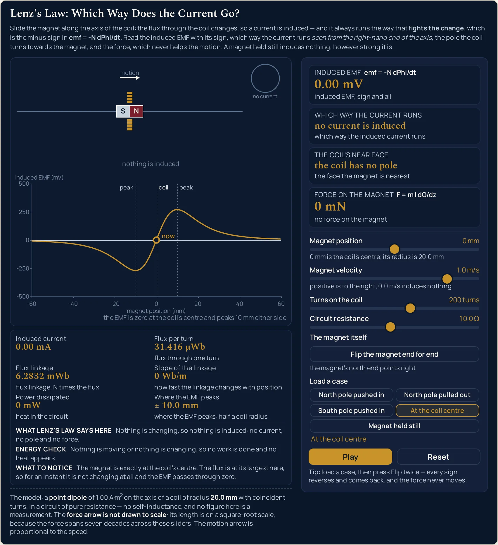
| Reverse the motion to -1.0 m/s | -10 mm · -1.0 m/s | 200 turns · 10.0 Ω | 269.75 mV | anticlockwise, seen from the right | the coil's near face is a south pole | 7.28 mN |
| Flip the magnet instead, still pushing in | -10 mm · 1.0 m/s | 200 turns · 10.0 Ω | 269.75 mV | anticlockwise, seen from the right | the coil's near face is a south pole | 7.28 mN |
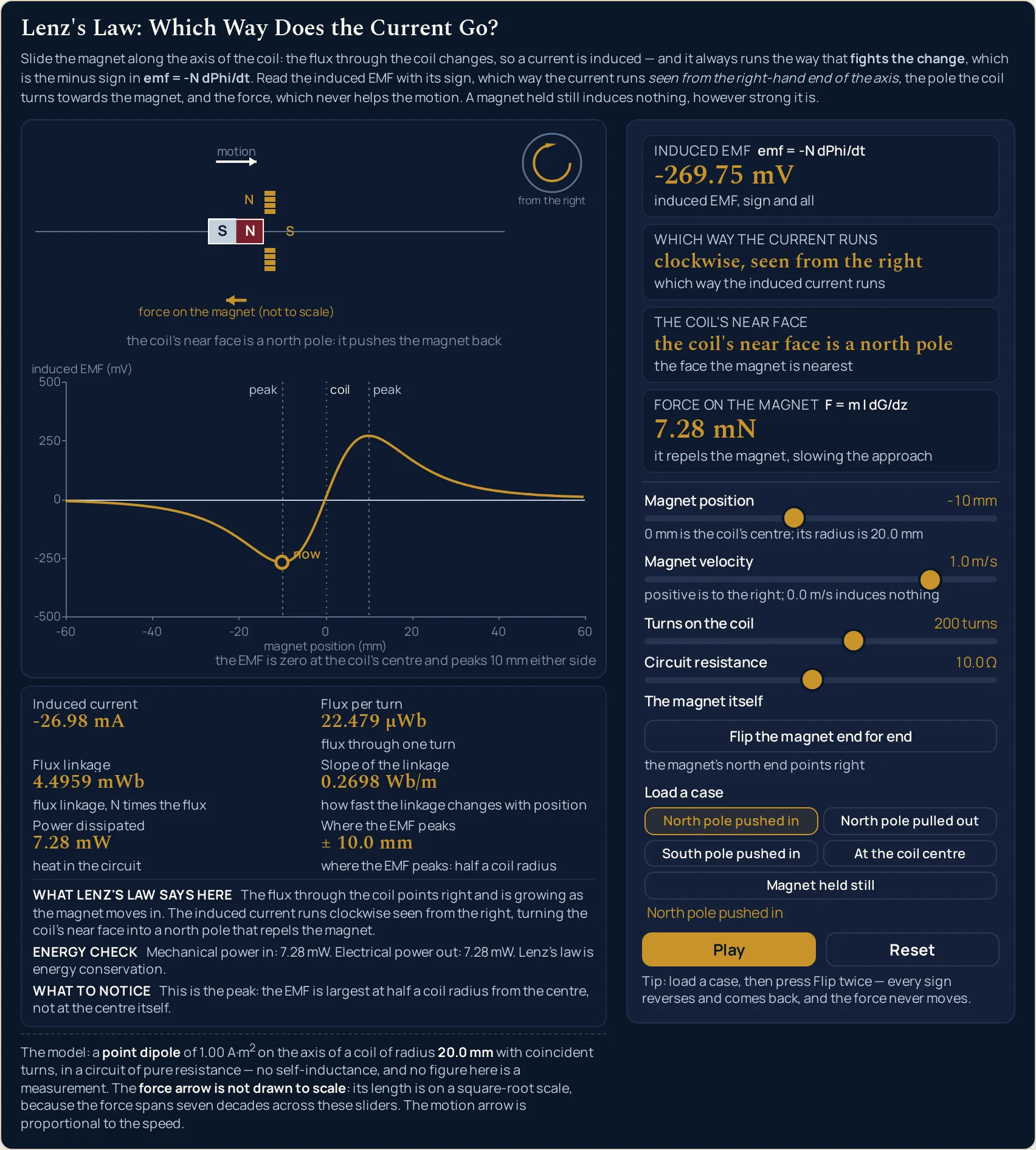
| Slide the magnet to the centre, z = 0 mm | 0 mm · 1.0 m/s | 200 turns · 10.0 Ω | 0.00 mV | no current is induced | the coil has no pole | 0 mN |
| Drop the circuit to a 1.0 ohm load | -10 mm · 1.0 m/s | 200 turns · 1.0 Ω | -269.75 mV | clockwise, seen from the right | the coil's near face is a north pole | 72.8 mN |
Row 2 shows that the direction follows the change, not the field. Nothing about the magnet or the coil has moved; only the sign of the velocity. Yet the EMF goes from “-269.75 mV” to “269.75 mV”, the current turns the other way round the loop, and the face the coil presents changes from north to south. The caption under the force changes with it, from it repels the magnet, slowing the approach to it attracts the magnet, slowing the retreat.
Row 3 shows that the force does not care which pole leads. Flipping the magnet reverses every signed reading, exactly as reversing the motion did — and leaves Force on the magnet at “7.28 mN”, still repelling. Two changes that look opposite give the same push, because the force carries the square of the linkage slope. Press Flip twice and every reading returns to where it started.
Row 4 shows that the biggest flux is where the EMF is nothing. At the centre Flux per turn reaches “31.416 µWb”, the largest value it takes anywhere on the axis, while Slope of the linkage reads “0 Wb/m” and the EMF, the current and the force all print zero together. That is the trap this lab exists to spring: the Faraday's law formula reads a rate, never an amount.
Row 5 shows what the load does and does not do. A tenth of the resistance gives ten times the current, the force and the heat, and leaves the EMF at “-269.75 mV”, unmoved to the last digit. That ten is the algebra of I = ε/R with the EMF fixed, not the quotient of the printed “-269.75 mA” and “-26.98 mA”, which are rounded to two decimals and divide to 9.998. If you want that EMF worked out from a flux change of your own instead of read off a slider, the Faraday's law calculator does that arithmetic; it reports the size, and the sign is what this lab is for.
Ratios belong to the formulae, not to the printed strings. Force on the magnet carries three significant figures, so 200 turns give “7.28 mN” and 300 turns give “16.4 mN”. Dividing those two rounded readings does not give the true factor. The force goes as the square of the turns, so the honest factor is the square of 300/200, which is 2.25; reading it off the panel instead is how a correct experiment yields a wrong number.
Formula and symbol reference
The lab works out the flux a point dipole sends through one turn at the magnet's position, multiplies by the turns to get the linkage, differentiates that with respect to position to get the slope, and multiplies the slope by the velocity for the EMF. Ranges marked “in this lab” are the controls' own ends and the strings the lab prints there.
| Symbol | Meaning | SI unit | In this lab |
|---|---|---|---|
| ε | Induced EMF: what the changing flux linkage drives round the circuit, sign and all | volt, V (printed in mV) | Two decimals in millivolts, from “-606.94 mV” to “606.94 mV” at the corners of the sliders. “0.00 mV” appears only where the EMF is exactly zero — at 0.0 m/s or at 0 mm — and the smallest non-zero reading anywhere is “-0.22 mV”. |
| Φ | Magnetic flux through one turn of the coil | weber, Wb (printed in µWb) | Three decimals in microwebers, from “31.416 µWb” at the coil centre down to “0.993 µWb” at either end of the position slider. It is never zero, and the turns slider never moves it. |
| NΦ | Flux linkage: the flux multiplied by the number of turns it threads | weber, Wb (printed in mWb) | Four decimals in milliwebers, from “0.0497 mWb” (50 turns, 60 mm out) to “9.4248 mWb” (300 turns at the centre). “4.4959 mWb” after Reset. |
| d(NΦ)/dz | Slope of the flux linkage with position — the quantity the EMF actually follows | weber per metre, Wb/m | Four significant figures, from “0.002235 Wb/m” at the quietest setting to “0.4046 Wb/m” at 300 turns and 10 mm out. Exactly “0 Wb/m” at the coil centre, at every turn count. |
| I | Induced current: the EMF divided by the circuit resistance | ampere, A (printed in mA) | Two decimals in milliamps, from “-606.94 mA” to “606.94 mA”. Positive means anticlockwise seen from the right-hand end of the axis, which is the sign convention behind every direction on this page. |
| F | Force on the magnet along the axis | newton, N (printed in mN) | Three significant figures in millinewtons, from “0.0000250 mN” to “246 mN”, with a plain “0 mN” when nothing is induced. The caption under it says whether it repels or attracts; it never says it helps. |
| P | Heat dissipated in the circuit | watt, W (printed in mW) | Three significant figures in milliwatts, from “0.00000250 mW” to “368 mW”. The Energy check line prints this figure twice over, once as mechanical power in and once as electrical power out. |
| z | Magnet position, measured from the coil centre along the axis | metre, m (shown in mm) | -60 to +60 mm in steps of 5 mm; -10 mm after Reset. Positive is to the right, and 0 mm is the centre of the coil. |
| v | Magnet velocity along the axis | metre per second, m/s | -1.5 to +1.5 m/s in steps of 0.1, printed to one decimal; +1.0 m/s after Reset. At “0.0 m/s” six readouts go to nothing together, however the other three sliders are set. |
| N | Number of turns on the coil | none (a count) | 50 to 300 turns in steps of 10; 200 turns after Reset. It scales the EMF and the current, and the force by the square of that — but it leaves the flux through one turn exactly where it was. |
| R | Total resistance of the circuit | ohm, Ω | 1.0 to 20.0 Ω in steps of 0.5, printed to one decimal; 10.0 Ω after Reset. The only slider that moves the current, the force and the heat without touching the EMF. |
| a | Coil radius: the lab's fixed geometry, not a control | metre, m (shown in mm) | Fixed at 20.0 mm. Where the EMF peaks reads “± 10.0 mm” at every setting of every control, because the peaks sit at half a coil radius. |
| m | Dipole moment of the magnet | ampere square metre, A·m² | Fixed at 1.00 A·m². Only its sign is under your control, through the Flip button; no slider touches it. |
| μ0 | Magnetic constant, mu-nought, in the flux formula | tesla metre per ampere, T·m/A | Fixed at 4π × 10-7 T·m/A, the conventional value. It is a measured quantity since the 2019 revision of the SI, but it departs from that figure far below any digit this lab prints. |
The physics: why the current always fights the change
The quantity that matters is not the field at the coil but the flux linkage through it — the flux through one turn multiplied by the number of turns. Flux linkage and Slope of the linkage sit side by side in the lab precisely so you can watch them disagree. Drag the position slider and the linkage rises to a single hump peaking at the centre, while its slope rises, falls back through zero at that peak and comes out the other side with the opposite sign.
The EMF is that slope multiplied by the velocity, with a minus in front. So the two ways of making a bigger EMF are a steeper slope and a faster magnet, and neither of them is “a stronger field” on its own. At 10 mm out with 300 turns the slope reads “0.4046 Wb/m”; at 60 mm out with 50 turns it reads “0.002235 Wb/m”, and the EMF collapses with it. The magnetic field of the dipole is what sets that slope in the first place.
The sign convention is fixed once and used everywhere: a positive current runs anticlockwise seen from the right-hand end of the axis. That is why Which way the current runs carries the viewpoint inside the string rather than beside it. The coil's near face is a north pole exactly when the polarity and the velocity have the same sign, and a south pole when they differ. Three of the five case buttons cover three of those four sign pairings; the fourth, south end leading and moving away, is North pole pulled out plus one press of Flip, while At the coil centre and Magnet held still print the coil has no pole.
Then look at Energy check. It prints the mechanical power you are putting in and the electrical power coming out as heat, worked out on two separate lines of the code, and they agree at every setting: “Mechanical power in: 7.28 mW. Electrical power out: 7.28 mW.” That identity is the whole content of the minus sign. Reverse the direction rule and the same two numbers would have opposite signs, which is a machine that pays for nothing.
Where this model breaks down
The lab solves its own model exactly, so nothing on screen ever fails. Every limit below is a limit of the model or of the drawing, and each item says what the lab does about it.
- The magnet is a point, and a real bar magnet is not
- The flux formula here is the exact one for a point dipole on the axis. A real magnet has length, and once it sits closer to the coil than that length — let alone threaded through it — the true flux parts company with this curve. That is the region the position slider spends most of its travel in, so treat the shape of the curve near the centre as the model's shape rather than a measurement. What survives the approximation is the structure: a hump in the linkage, a zero in the slope at its summit, and peaks either side.
- The turns are all in the same place
- All 200 turns are treated as sitting at 0 mm, so the coil has a radius but no length. A real winding is spread along the axis, which smooths the EMF curve and moves the peaks a little; nothing here models that, and the lab does not draw a turn count either — the coil keeps four cross-sections a side whatever the turns slider says, so that nothing on the bench implies a number. A coil with genuine length is what the solenoid simulator is built around.
- The circuit has no self-inductance
- The current here follows the EMF instantly, because the circuit is a pure resistance. A real coil opposes changes in its own current as well, which delays and reduces it at high speed, so the fastest settings on the velocity slider are the ones this model flatters most. The lab states the omission in the line under the canvas and quantifies nothing, because nothing about it was computed for this cluster.
- The force arrow is not a measurement
- Its label says so: force on the magnet (not to scale), shortening to force (not to scale) when the canvas is narrow. Because the force spans about seven decades between the corners of the sliders, every arrow the lab draws begins at a fixed minimum length and then grows with the square root of the force, reaching full width at “246 mN”. A minimum plus a square root squeezes seven decades into a few-fold change in length, so an arrow twice as long is nothing like twice the force. Read the force from Force on the magnet, never from the picture; the motion arrow above the magnet is the one that is proportional.
- Nothing here predicts what a falling magnet would do
- The velocity slider is something you set, not something the lab works out. It never integrates the motion, so it cannot tell you a terminal speed, a stopping distance or how long a magnet takes to fall through anything. The forces are small in any case: the largest the sliders can reach is “246 mN”, at 300 turns, a 1.0 Ω circuit and 1.5 m/s, and the default push is “7.28 mN”. The famous copper-pipe demonstration is the same principle in a different geometry — currents circulating in bulk metal rather than round a wire — and it gets no numbers here.
- What the drawing leaves out when there is no room
- Every string on the canvas is measured before it is drawn, then shortened or dropped rather than overprinted. At the width this page gives it the scene caption reads in full — the coil's near face is a north pole: it pushes the magnet back — and so does the chart caption, the EMF is zero at the coil's centre and peaks 10 mm either side. Squeezed into a narrow article column the two degrade to near face north: pushes it back and peaks 10 mm either side, the inset is dropped, and the tick ladder thins by a whole factor rather than losing a middle rung.
- The lab's own arithmetic and display
- Three significant figures on the force, the heat and the slope; two decimals on the EMF and the current; three on the flux and four on the linkage. A reading that is exactly zero prints “0.00 mV” or a bare “0 mN”, never a negative zero, and those strings appear only where the EMF really is zero — the smallest non-zero reading anywhere on the grid is “-0.22 mV”. Because everything is rounded for display, a ratio taken between two printed figures is not the ratio the physics gives.
Where Lenz's law is actually used
- Generators, dynamos and the cost of switching on a load
- The resistance slider is this idea in miniature. An open circuit is an enormous resistance: an EMF appears, almost no current flows, and there is almost nothing to push against. Close the circuit and the current, the force and the heat all arrive together — dropping from 10.0 Ω to 1.0 Ω takes the force from “7.28 mN” to “72.8 mN” while the EMF does not move. That extra effort at the handle is the electrical power, and the Energy check line is the receipt.
- Magnetic braking on trains, rides and gym equipment
- Press North pole pushed in and then North pole pulled out: the force reverses direction but keeps its size, because it is always set against the motion. That is exactly the property a brake wants and a drive does not. It also explains the characteristic feel of these brakes — the force falls away as the relative speed does, so they ease off smoothly rather than grabbing, which is what the velocity slider shows as you walk it back towards “0.0 m/s”.
- Induction hobs and metal detectors
- Both throw a rapidly changing field at a conductor and live off whatever circulates inside it — a hob to warm the base of a pan, a detector to pick out a coin under the soil. The changing part is everything: hold the field still, however strong it is, and neither works at all. Press Magnet held still and watch six readouts go to nothing together while Flux per turn stays at “22.479 µWb” — a large, perfectly steady flux driving precisely nothing.
- Transformer and coil design
- The turns slider is the designer's main lever, and this lab shows its two faces. Going from 200 to 300 turns takes the EMF from “-269.75 mV” to “-404.63 mV” and the heat from “7.28 mW” to “16.4 mW”, because the EMF scales with the turns and the power with their square. Flux per turn meanwhile sits at “22.479 µWb” whatever you do, which is why a coil is specified by its linkage and not by the flux it happens to sit in.
- Damping in a moving-coil meter
- A meter needle that swung freely would oscillate for a long time before settling. Its own coil moving in the instrument's field induces a current, and that current opposes the motion that made it, so the needle arrives and stops. The three-step reasoning behind that — which way the flux is going, which way the induced field must point, which way the current therefore runs — is set out in the three-step rule for finding the direction of an induced current.
Where to go next
The full account — the definition, where the minus sign comes from, the three-step direction rule, the four cases in a table, six worked problems and the energy argument — is in the article Lenz's Law Explained. When you need the size of an induced EMF rather than its direction, use the Faraday's law calculator: it models a uniform field changing across a flat area, and works out whichever one of its five quantities — EMF, turns, area, field change, elapsed time — you leave for it. It reports a magnitude, so read the sign off this lab.
For the background, electromagnetic induction covers the effect as a whole and the Faraday's law formula takes the algebra of the size apart. The electromagnetic induction simulator drives a coil sinusoidally and answers “how big?”, while the magnetic field simulator and the solenoid simulator draw the fields underneath all of it. The rest are in the library of physics simulations.
Frequently asked questions
Why does the force stay at 7.28 mN when I flip the magnet?
Because the force depends on the square of the linkage slope, so reversing that slope cannot reach it. Press Flip on the default setting and Induced EMF goes from -269.75 mV to 269.75 mV, Induced current from -26.98 mA to 26.98 mA, and the near face from a north pole to a south pole. Force on the magnet holds at 7.28 mN, still repelling. Press Flip again and every sign returns.
Why is the induced EMF zero when the magnet sits at the coil centre?
Because the EMF follows the slope of the flux linkage rather than its size. Press At the coil centre and Flux per turn rises to the largest value it reaches anywhere, 31.416 µWb, while Slope of the linkage reads 0 Wb/m. Induced EMF therefore prints 0.00 mV, Induced current 0.00 mA and Force on the magnet 0 mN. Largest is not the same as changing fastest.
Why does the resistance slider never move the induced EMF?
Because the EMF is made by the changing flux linkage, before the circuit has any say in it. Drag Circuit resistance across all 39 of its positions on the default setting and Induced EMF holds at -269.75 mV throughout, while Induced current, Force on the magnet and Power dissipated all change. Drop the load to 1.0 Ω and the current reads -269.75 mA with a force of 72.8 mN.
Why does the case line say custom setting after I move a slider?
Because a named case is an exact setting, and touching any control means you have left it. The line under the case buttons reads a name such as North pole pulled out only while the magnet is exactly where that button put it. Move any of the four sliders, or press Flip, and it reverts to custom setting. So do the first load of the page and the Reset button.
Which way is clockwise in this lab?
As seen from the right-hand end of the axis, looking back along it towards the magnet. Every direction the lab prints carries that viewpoint inline, because a rotation sense means nothing without one: on the default push, Which way the current runs reads clockwise, seen from the right. The small circle at the top right of the bench shows the same sense end-on, captioned from the right.
Why does the force arrow barely grow when the force grows a hundredfold?
Because the force arrow is drawn on a square-root scale, and its own label says force on the magnet (not to scale). The force spans about seven decades across these sliders, from 0.0000250 mN at the quietest corner to 246 mN at the loudest, so a proportional arrow would be invisible at one end and off the canvas at the other. The motion arrow, by contrast, is strictly proportional to the speed.
Does pausing the animation change any of the readings?
No. Nothing the lab reports depends on time, so Pause rests the loop and leaves the scene exactly as drawn. What stops is the circular arrow in the end-on inset and the cream highlight that walks round the coil's turn marks; both also stop on their own whenever no current is induced. Every slider and button still works while the lab is paused.
Why does a case button not change the turns or the resistance?
Because each case is a statement about the magnet, not about the coil or the circuit. The five buttons set the position, the velocity and which end points right, and nothing else, so whatever you wound onto the coil survives a change of case. Wind 300 turns, drop the circuit to 1.0 Ω, then press North pole pulled out: the panel still reads 300 turns and 1.0 Ω.
References & formula source
- Halliday, Resnick and Walker, Fundamentals of Physics: Induction and Inductance, where Faraday's law is stated with its minus sign and Lenz's law is derived as the direction rule that sign encodes.
- Young and Freedman, University Physics: Faraday's Law and Lenz's Law, including the energy argument and the motional-EMF treatment of a conductor moving in a field.
- Griffiths, Introduction to Electrodynamics: Electrodynamics, Faraday's Law, for the field-theoretic statement and the sign convention that ties a positive current to a chosen surface normal.
- Every figure on this page is an output of the lab's point-dipole model, traceable to the cluster's reference tables, and none of them is a measurement of a real magnet or coil; verify against your own apparatus before use.
- Further reading: Lenz's law — Wikipedia