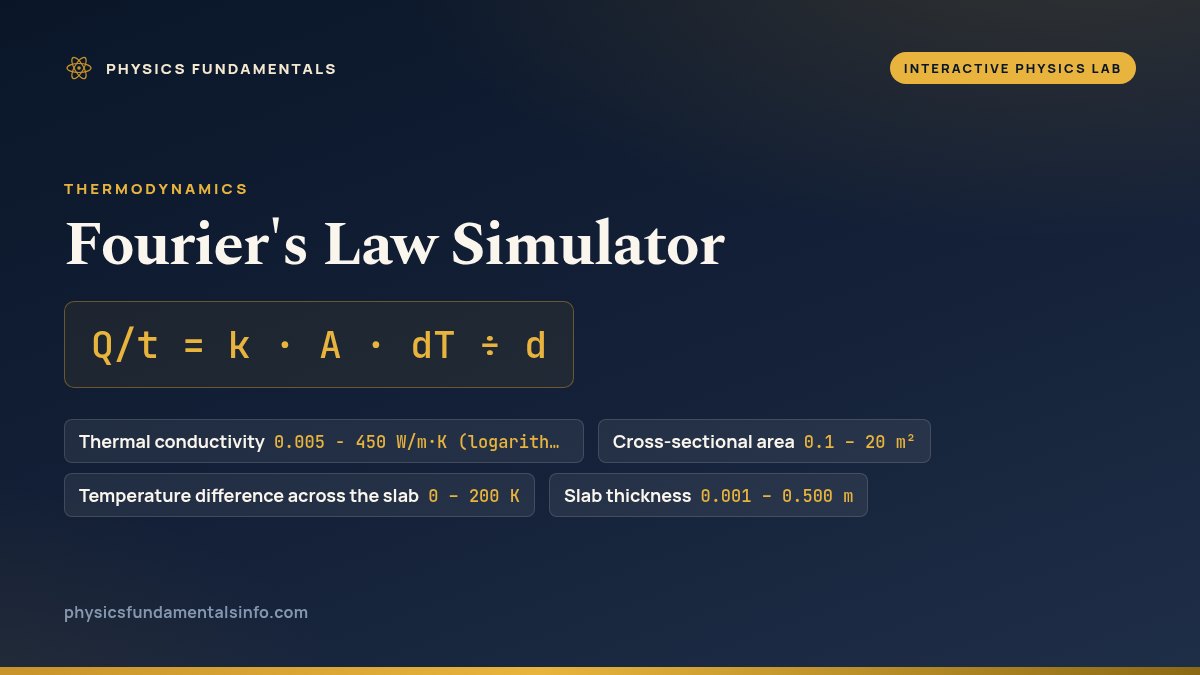
Fourier's law sets the rate at which heat conducts through a slab: Q/t = k · A · dT ÷ d. Drag the four sliders below to change the conductivity, area, temperature difference and thickness, or jump straight between aerogel, mineral wool, wood, brick and copper, and watch the heat-flow rate in watts respond.
Fourier's Law: Heat Through a Slab
One face is hot, the other is cold, and heat crosses the material in between at a rate set by Q/t = k · A · dT ÷ d. Drag the four sliders, or jump the conductivity between real materials, and watch the watts respond.
What Is the Fourier's Law Simulator?
The Fourier's law simulator is a free interactive physics lab that runs in your browser — nothing to install and no sign-up. Drag conductivity, area, thickness and temperature difference and watch the heat-loss rate in watts update live. It reports Heat-flow rate Q/t as you drag the sliders.
| Control | Range | Step |
|---|---|---|
| Thermal conductivity | 0.005 - 450 W/m·K (logarithmic) | — |
| Cross-sectional area | 0.1 – 20 m² | 0.1 |
| Temperature difference across the slab | 0 – 200 K | 1 |
| Slab thickness | 0.001 – 0.500 m | 0.001 |
What Each Slider Does to the Watt Reading
Three of the four sliders push the headline number the same way. Conductivity, area and temperature difference all multiply the rate, so doubling any one of them doubles the watts and closing the temperature gap to zero stops the flow dead, whatever the other three are set to. Thickness is the odd one out: it divides. That single difference is the whole shape of the tool.
The conductivity slider is spaced by powers of ten rather than evenly, because the materials it covers run from aerogel at 0.015 to copper at 401 watts per metre per kelvin — more than four orders of magnitude. On an evenly spaced track, every insulator worth comparing would sit within the first pixel or two of travel. Spacing it logarithmically gives each decade the same width, so the same nudge always means the same multiplying factor. The five preset buttons snap k onto published figures exactly, which the slider's own step grid cannot quite do; the guide to Fourier's law of thermal conduction names the equation behind them and works through where each symbol comes from.
The thermal resistance R and U-value readouts are not extra physics. They are the same slab described as an obstacle rather than as a flow: R is thickness divided by conductivity, and U is one divided by R. A rate answers "how many watts is this wall losing right now"; a resistance answers "how good is this wall, whatever its size and today's weather". That is why engineers quote U. When you need a specific figure rather than a feel for the trend, the thermal conduction calculator gives you an exact number and rearranges the formula for whichever quantity you are missing.
The misconception the sim is built to correct lives on the thickness slider. Most people expect insulation to work in a straight line: twice as thick, half the loss, and another equal layer halving it again. Watch the watt readout as you step d along evenly and you will see the drop shrink each time — a 20 mm addition to a thin wall is transformative, and the same 20 mm on a thick one is nearly invisible. That is what dividing by d looks like. One caveat on scope: the arrows show conduction only, so nothing here accounts for air moving against either face or the surfaces radiating — the guide to conduction, convection and radiation separates those out.
Frequently asked questions
What does the conductivity slider actually change?
It changes k, the material's thermal conductivity, in watts per metre per kelvin. Everything else about the slab stays exactly as you set it; only the material changes. Because k multiplies the rate directly, doubling it doubles the watts. The five preset buttons park k on real published figures - aerogel at 0.015, mineral wool at 0.040, wood at 0.13, brick at 0.72 and copper at 401 - so you can jump between materials without hunting for the value on the slider.
Why does the heat-loss readout drop more slowly as I increase thickness?
Because thickness sits in the denominator. The rate is proportional to 1/d, not to d, so equal steps of the slider are not equal steps of heat saved. Going from 20 mm to 40 mm halves the rate; going from 200 mm to 220 mm, the same 20 mm of extra material, barely moves it. That curve is why insulation specifications reach a point where another layer stops paying for itself, and it is the single most useful thing this simulator shows.
What is the difference between the Q/t readout and the U-value readout?
They are the same physics written two ways. Q/t is a rate: how many joules cross this particular slab every second, so it depends on how big the slab is and how large the temperature gap is. The U-value is a property of the construction alone, in watts per square metre per kelvin, and it is simply 1 divided by the thermal resistance R = d/k. Multiply U by the area and by the temperature difference and you get Q/t back. Builders quote U because it lets two walls be compared without knowing either wall's size or the weather.
Can I use this simulator for convection or radiation?
No. This lab models conduction only - heat carried through a solid in contact, in one dimension, at steady state. Real walls also lose heat by convection to the air on each side and by radiation from their surfaces, and those add their own resistances in series with the one shown here. The conduction figure is therefore an upper bound on what the material alone contributes, not a full heat-loss budget for a building.
Why is the k slider spaced logarithmically?
Because the materials span roughly four and a half orders of magnitude, from aerogel near 0.015 to copper at 401 watts per metre per kelvin. On a linear slider, everything from aerogel to brick would be crushed into the first fifth of a percent of the travel and you could not separate an insulator from a timber joist. Spacing the slider by the logarithm of k gives every decade the same amount of travel, so a step of the same size always means the same multiplying factor.
References & formula source
- Incropera & DeWitt — Fundamentals of Heat and Mass Transfer, Chapter 1 (the conduction rate equation) and Chapter 3 (one-dimensional, steady-state conduction through a plane wall).
- Çengel & Ghajar — Heat and Mass Transfer: Fundamentals and Applications, Chapter 1 (Fourier's law of heat conduction) and Chapter 3 (the thermal-resistance network).
- Young & Freedman — University Physics with Modern Physics, §17.7 (Mechanisms of Heat Transfer: Conduction).
- ISO 6946 — Building components and building elements: thermal resistance and thermal transmittance, the standard behind the R and U conventions.
- Further reading: Thermal conduction — Wikipedia