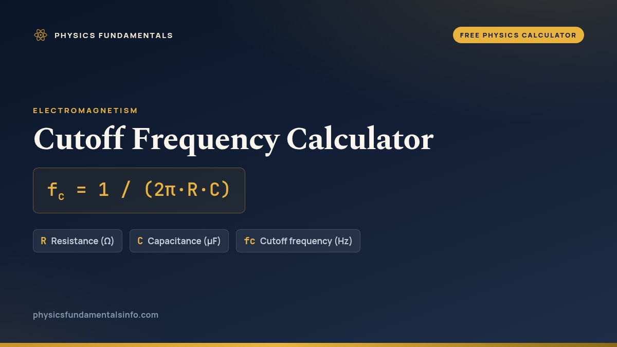
Cutoff frequency: the corner where an RC filter starts to attenuate — the -3 dB point at which the output falls to about 70.7% of the input, given by fc = 1/(2π·R·C). This free calculator solves for the frequency, the resistance or the capacitance, with every step shown.
What Is the Cutoff Frequency Calculator?
The cutoff frequency calculator is a free online tool built on the formula fc = 1 / (2π·R·C). Enter the values you already know, in whichever units suit you, and it solves for cutoff frequency, resistance or capacitance and shows every step of the substitution. Cutoff Frequency is the -3 dB corner frequency of an RC filter.
| Symbol | Quantity | Default unit | Also accepts | Example value |
|---|---|---|---|---|
| R | Resistance | Ω | kΩ, MΩ | 1000 |
| C | Capacitance | µF | nF, pF, F | 0.1 |
| fc | Cutoff frequency | Hz | kHz, MHz | — |
How to calculate cutoff frequency
For a first-order RC filter — whether low-pass or high-pass — the cutoff frequency is fc = 1/(2π·R·C), where R is the resistance in ohms and C is the capacitance in farads. This corner is the point where the reactance of the capacitor equals the resistance, so the two contribute equally to the circuit's response. Below the corner an RC low-pass filter passes the signal almost unchanged; above it, the output rolls off at 20 dB per decade.
Using the calculator is straightforward. Choose whether you want the frequency, the resistance or the capacitance in the Solve for menu, then enter the values you know. Type the resistance and the capacitance and read off the cutoff frequency directly, or work backwards and solve for R or C to hit a target corner. Every result is shown with the formula, your numbers substituted in, and the answer in the units you chose.
Because the frequency depends on the product R·C, the same corner can be reached with a large resistor and a small capacitor or the other way round — useful when a particular component value is easier to source. The reactance-balance idea is closely tied to the charging time of the circuit, which you can explore with the RC time constant calculator. To pick a suitable capacitor, see the capacitance calculator, and for the term itself see the physics glossary.
Worked example
Suppose you build an RC filter with a resistance of R = 1 kΩ and a capacitance of C = 0.1 µF. The cutoff frequency is fc = 1/(2π × 1000 × 1e-7), which works out to about 1592 Hz — a typical audio filter corner sitting comfortably in the middle of the hearing range. If you halve either the resistance or the capacitance, the product R·C halves and the cutoff frequency doubles to roughly 3183 Hz, so you can shift the corner simply by changing one component.
Why it matters
The cutoff frequency defines the behaviour of an enormous range of circuits: tone controls and equalisers in audio gear, the crossover networks that split signals between woofers and tweeters, the anti-aliasing filters in front of analogue-to-digital converters, and the noise filters that clean up sensor readings. It also sets the bandwidth of amplifiers and the response time of measurement systems. The same corner-frequency idea extends beyond RC circuits: an RL filter has fc = R/(2πL), while a resonant LC filter has fc = 1/(2π·sqrt(LC)). To choose the resistors that set these corners, try the resistor calculator.
Frequently asked questions
What is the cutoff frequency of a filter?
The cutoff frequency is the frequency where the output power drops to half of the input — the -3 dB point, where the output voltage falls to about 70.7% of the input. For a first-order RC filter it is given by fc = 1/(2 pi R C), with R in ohms and C in farads.
Is this for a low-pass or high-pass filter?
Both. The same formula fc = 1/(2 pi R C) sets the corner frequency for a first-order RC low-pass filter and a first-order RC high-pass filter. Only which side of the corner is passed differs: a low-pass filter keeps frequencies below fc, a high-pass filter keeps those above it.
How is cutoff frequency related to the RC time constant?
The RC time constant is tau = R C, measured in seconds, and the cutoff frequency is fc = 1/(2 pi tau). A longer time constant therefore means a lower cutoff frequency, because the filter responds more slowly to change.
What is the -3 dB point?
The -3 dB point is the frequency at which the output amplitude has fallen to 1/sqrt(2) of the input, about 0.707, which corresponds to exactly half the power. This is the standard definition of the cutoff or corner frequency of a filter.
How do I find the cutoff of an LC or RL filter?
For an LC filter the resonant cutoff is fc = 1/(2 pi sqrt(L C)), which depends on inductance and capacitance. For an RL filter the corner is fc = R/(2 pi L). In each case the corner is where the reactance balances the resistance in the circuit.
References & formula source
- Halliday, Resnick & Walker — Fundamentals of Physics, Chapter 31 (Electromagnetic Oscillations and AC).
- Young & Freedman — University Physics with Modern Physics, §31 (Alternating Current).
- Horowitz & Hill — The Art of Electronics, Chapter 1 (Filters).
- Further reading: Cutoff frequency — Wikipedia