across R1
4.000 V
Potential difference (voltage) is the energy given to each coulomb of charge, V = W/Q. Drag the sliders below to set the supply p.d., the two resistances and the charge, and watch the volts drop step-by-step down a series circuit — the drops always adding back to the supply.
A charge starts at the supply p.d. and steps down to 0 V, giving up energy across each resistor. The volts split between R1 and R2 but always add back to the supply — that is Kirchhoff's loop rule, and it proves voltage is energy per coulomb.
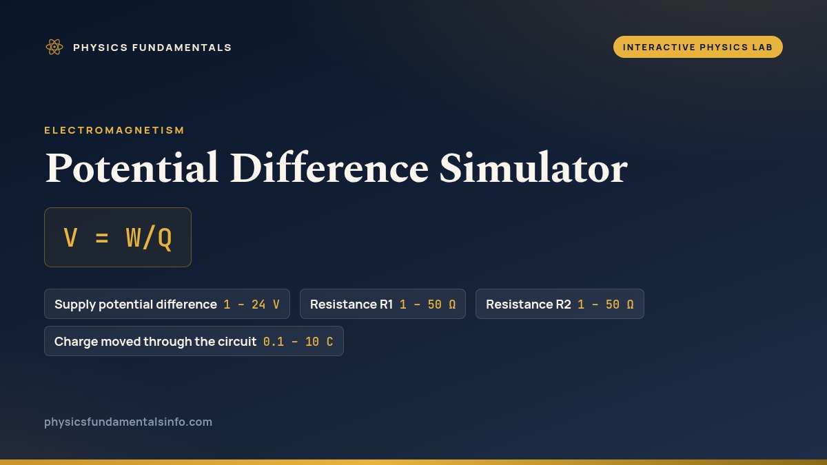
The potential difference simulator is a free interactive physics lab that runs in your browser — nothing to install and no sign-up. Drag the supply, resistance and charge sliders to see how volts split across a series circuit and why V = W/Q. It reports Current as you drag the sliders.
| Control | Range | Step |
|---|---|---|
| Supply potential difference | 1 – 24 V | 0.5 |
| Resistance R1 | 1 – 50 Ω | 1 |
| Resistance R2 | 1 – 50 Ω | 1 |
| Charge moved through the circuit | 0.1 – 10 C | 0.1 |
This simulator draws a series circuit as a potential staircase. A charge begins at the top, holding the full supply potential, then steps down across each resistor until it reaches zero volts at the far terminal. Every slider reshapes that staircase in a different way, and reading them together is the fastest route to understanding what voltage really is.
The Supply p.d. slider sets the height of the whole staircase. Raise it and the shared current climbs with it, so both drops — V1 across R1 and V2 across R2 — grow in proportion while their sum tracks the supply exactly. The R1 and R2 sliders redistribute the same total between the two steps: increase R1 and it seizes a bigger share of the volts, which forces V2 down by precisely the amount V1 gained. Under the hood the sim does what any circuit solver does — it computes the current from I = V/(R1+R2), then applies V = IR to each resistor — so the readouts you see are the loop rule and Ohm's law working together.
The Charge slider is the one that overturns a stubborn misconception. Drag it and the energy each resistor absorbs, W1 and W2, scales straight up — yet every voltage on the panel refuses to budge. That is because the V1 + V2 readout is not measuring a hoard of volts being spent; it is Kirchhoff's voltage law made visible, the guarantee that the drops always re-sum to the supply. Voltage is energy per coulomb, so pushing more coulombs through moves more joules without changing the ratio. Once that clicks, the definition V = W/Q stops being a formula to memorise and becomes something you have watched hold true. Put numbers to it with the potential difference calculator, read the full theory in What Is Potential Difference (Voltage)?, connect it to current and resistance via Ohm's law, or open another model from the full simulation collection.
Start with the supply. Whatever load you hang on it, this source holds the voltage you dialled: push both resistances to 1 Ω at 24 V and the readout reports 12.000 A with the supply sitting unmoved. No real cell does that. Every source carries internal resistance in series inside its own case, so the terminal p.d. sags to V − I·r as soon as current flows. Read R1 as that internal resistance and the simulator shows you the size of it: at 24 V with R1 = 1 Ω and R2 = 50 Ω, the load receives only V2 = 23.529 V, and the missing 0.471 V is burnt inside the battery. That resistance climbs as a cell discharges, which is why a nearly-flat battery reads full on a meter and dies under load.
The connecting wires have no resistance at all here, so the staircase runs dead flat between the resistors. Real copper, connectors, solder joints and a corroded earth strap each add a fraction of an ohm, and the loop rule treats them like any other resistor: they take their share of the volts. That is why a long thin extension lead leaves a heater running cool, and why a dim headlight is usually a bad earth rather than a bad bulb.
The resistances are frozen too. Set 24 V across two 1 Ω resistors and the sim reports 12.000 A quite cheerfully — but 12 A through 1 Ω is I2R = 144 W in each resistor, hundreds of times what a quarter-watt component survives. Well below that limit resistance still drifts as a component warms, so a divider trimmed to the right split cold no longer holds it after a minute under load.
And a divider only divides while nothing is connected to the middle of it. Tap the junction between R1 and R2 to drive something, and whatever you connect sits in parallel with R2, drags the pair's combined resistance down and shifts the split away from your calculation. That is also why a voltmeter is built with an enormous internal resistance: to disturb the p.d. it is reading as little as possible.
Finally, the charge sliding down the staircase is a picture, not a mechanism. Carriers in a real wire drift at well under a millimetre per second while the energy arrives through the fields around the conductor. V = W/Q averages over an enormous population of carriers; it does not follow one of them.
Almost every microcontroller that measures its own battery uses this circuit. A 3.3 V chip cannot take 12 V on an input pin, so a divider scales the reading first. Set the supply to 12 V, R1 to 33 Ω and R2 to 12 Ω: the sim gives I = 0.267 A and V2 = 3.200 V, safely inside a 3.3 V input. The real board uses 33 kΩ and 12 kΩ instead — the ratio, and therefore the 3.200 V output, is identical, but the current falls a thousandfold, so the divider does not flatten the battery it monitors.
Turn the circuit around and it becomes a current meter. Put a small known resistance in series with a load and the p.d. across it reads the current directly. Set 5 V with R1 = 1 Ω and R2 = 9 Ω: V1 shows 0.500 V, and because R1 is exactly 1 Ω that figure is also the current, 0.500 A, which is what the I readout says. The cost sits in the same panel — the sense resistor has claimed 0.500 V of the 5 V, a tenth of the supply. Real shunts are milliohms for exactly that reason.
Swap R2 for something whose resistance tracks the world and the divider becomes a sensor. A car's coolant temperature sender is a thermistor in a divider on a steady 5 V rail, and the engine computer reads the junction voltage rather than the resistance. Hold R1 at 10 Ω on a 5 V supply and move R2: at 50 Ω the output V2 is 4.167 V; at 2 Ω it has fallen to 0.833 V.
Because potential difference is energy per unit charge, V = W/Q, not energy alone. When you drag the charge slider, the energy each resistor takes (W1 and W2) scales up in exact proportion, so the energy-per-coulomb ratio — the voltage — stays fixed. That is the whole point: voltage is not a stock that gets used up as more charge flows; it is a property of the two points, the same for one coulomb or a thousand.
The circuit is in series, so a single current flows through both resistors: I = V/(R1+R2). Raising R1 increases the total resistance, which lowers that shared current. A bigger R1 with a smaller current still claims a larger share of the supply (V1 = I·R1 rises), and because the two drops must add to the fixed supply, V2 = I·R2 falls by the same amount. The split shifts, but the total never changes.
It is Kirchhoff's voltage law — the loop rule — made visible. However you set the resistances, the two potential drops always sum to the supply p.d., because a charge that climbs to the supply potential must give all of that energy back by the time it returns to the negative terminal. The readout stays glued to the supply voltage no matter how you move the sliders.
No — this simulator models two resistors in series, sharing one current and splitting the supply voltage between them. In a parallel arrangement each branch instead sees the full supply voltage while the current splits between the branches, so the maths is different. Use this lab to master the series loop rule first; the ideas transfer once the series case is clear.
It solves the series circuit in two steps. First it finds the current from the supply and the total resistance, I = V/(R1+R2). Then it finds each potential drop with V = IR, giving V1 = I·R1 and V2 = I·R2. Finally the energy each resistor takes from a charge Q is W = QV, and dividing energy by charge returns the voltage, confirming V = W/Q.