Fluid pressure P
79.6 kPa
Pascal's law transmits pressure equally through a confined fluid, letting a hydraulic press multiply force: F2 = F1·(d2/d1)². Drag the sliders below to change the input force and the two piston diameters, and watch the fluid pressure and output force respond in real time.
Press the small piston and the pressure spreads equally through the fluid, pushing up on the large piston with far more force: F2 = F1·(A2/A1). You gain force but lose distance — the small piston travels much farther than the load rises.
Each button sets the three sliders to the bores of an actual piece of hydraulic equipment, then lets the simulator work out the rest. The confirmation line below quotes the lab's own readouts, not a stored answer.
Pick a machine above, or drag the sliders yourself.
The Pascal's law simulator is a free interactive physics lab that runs in your browser — nothing to install and no sign-up. Change the input force and piston diameters and watch a hydraulic press multiply force through F2 = F1(d2/d1)². It reports output force, fluid pressure and mechanical advantage as you drag the sliders.
| Control | Range | Step |
|---|---|---|
| Input force | 20 – 500 N | 5 |
| Small piston diameter | 2 – 10 cm | 0.1 |
| Large piston diameter | 10 – 40 cm | 0.5 |
P = F1/A1 — watch Fluid pressure P jump as you shrink it, and the fluid in the drawing change colour from blue through gold to deep red as the gauge climbs.m = F2/g.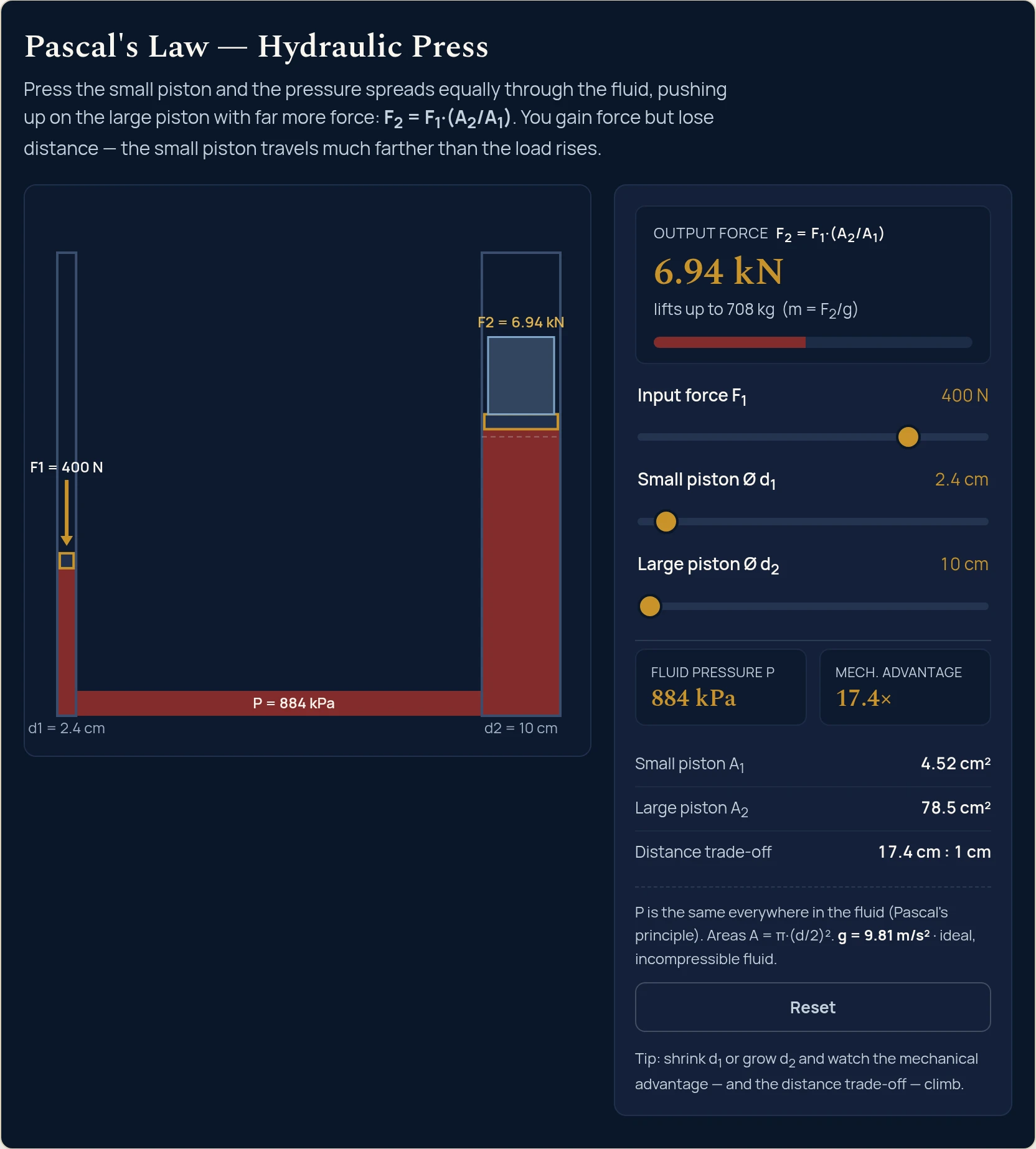
Start from the Reset state and move a single slider per step. Every figure in the table is the string the simulator itself printed for those slider positions — the values were read back out of the running lab, not worked out on paper, so if the table and the tool ever disagree, the tool is right.
| Step | Input F1 | Small bore | Large bore | Pressure P | Advantage | Output force F2 (mass held) |
|---|---|---|---|---|---|---|
| Start (Reset) | 100 N | 4 cm | 20 cm | 79.6 kPa | 25× | 2.5 kN (255 kg) |
| Push twice as hard | 200 N | 4 cm | 20 cm | 159 kPa | 25× | 5 kN (510 kg) |
| Halve the small piston | 200 N | 2 cm | 20 cm | 637 kPa | 100× | 20 kN (2040 kg) |
| Double the large piston | 200 N | 2 cm | 40 cm | 637 kPa | 400× | 80 kN (8150 kg) |
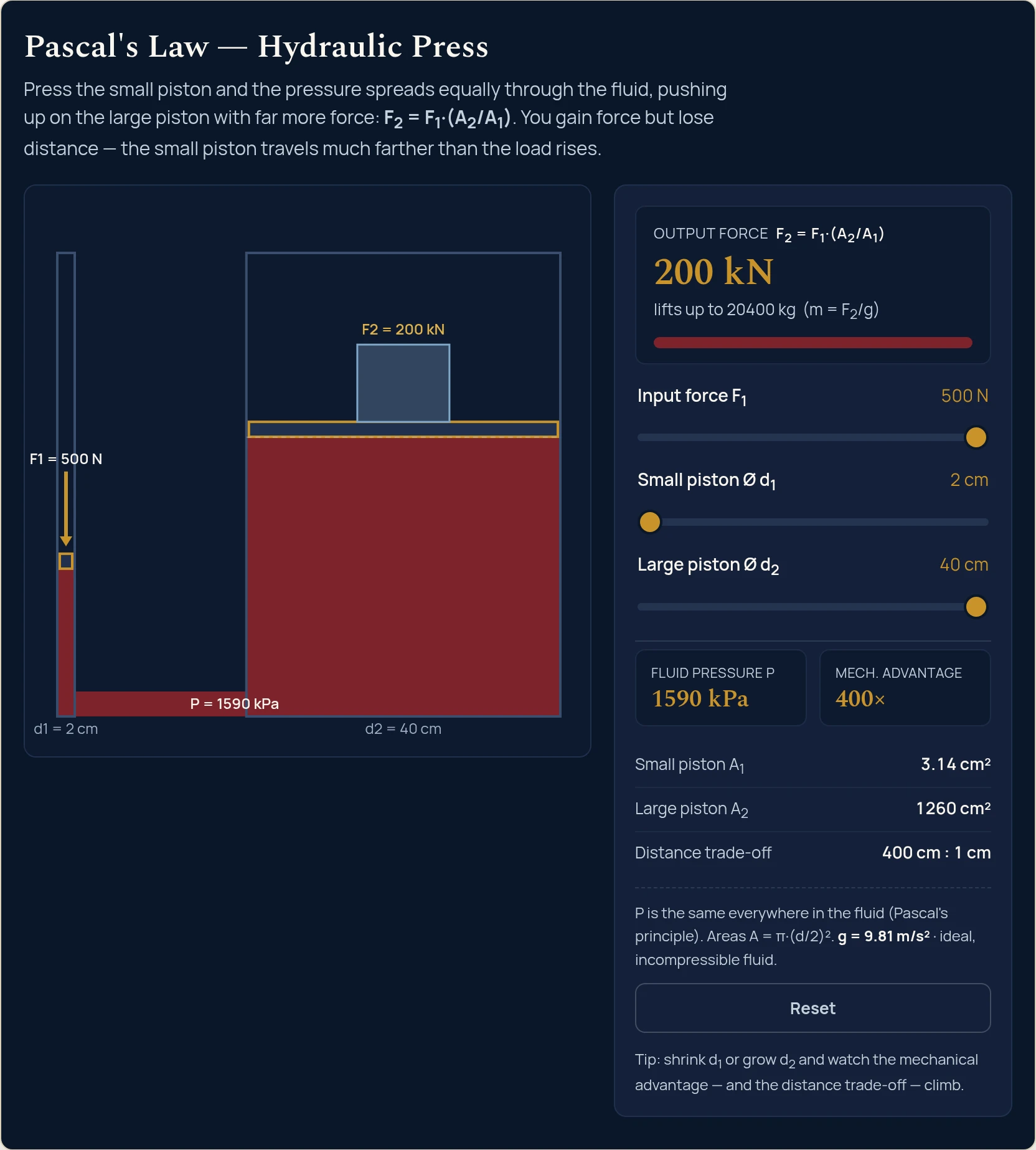
| Equal pistons | 200 N | 10 cm | 10 cm | 25.5 kPa | 1× | 200 N (20.4 kg) |
Read down the rows and the machine explains itself. Row 1 to row 2: doubling the push doubles the pressure and doubles the output, but the mechanical advantage does not budge. Geometry sets the multiplier; your hand only sets the scale. Row 2 to row 3: halving d1 from 4 cm to 2 cm cuts the input area from 12.6 cm² to 3.14 cm², so the pressure quadruples to 637 kPa and the output goes with it. Row 3 to row 4: doubling d2 from 20 cm to 40 cm quadruples the output area from 314 cm² to 1260 cm² and quadruples the force again — while the pressure does not move at all, because the output piston has no vote in what the pressure is. Row 5 is the control: with both bores at 10 cm the advantage is 1× and 200 N in gives 200 N out. Matched cylinders make a rigid rod that happens to bend round corners, which is exactly what a brake line is when the pistons are the same size.
The bill for all of it is in the last readout. The lab's Distance trade-off line shows 25 cm : 1 cm for rows 1 and 2, 100 cm : 1 cm for row 3 and 400 cm : 1 cm for row 4. At the row 4 setting a full metre of travel on the input piston lifts the load by two and a half millimetres. The 80 kN did not come from nowhere: it is the same joules, delivered over four hundred times less distance.
There are also two different ways to buy the same multiplier, and the simulator prices them differently. Hold F1 at 100 N and set d1 = 2 cm with d2 = 20 cm: you get 10 kN out at 318 kPa. Now get to the same 100× the other way, d1 = 4 cm with d2 = 40 cm: still 10 kN out, but now at 79.6 kPa. Identical force, a quarter of the pressure. That second number is the one an engineer actually designs around, because pressure is what bursts hoses and blows seals — force is only what the machine does for a living.
Everything the lab computes comes from three relationships: A = pi·(d/2)², P = F1/A1 and F2 = P·A2. The ranges marked “in this lab” are the simulator's own displayed values at the ends of its slider travel.
| Symbol | Meaning | SI unit | Typical range |
|---|---|---|---|
| F1 | Force applied to the small (input) piston | newton, N | 20 to 500 N in this lab. A firm two-handed push on a jack handle is 200 to 400 N. |
| d1 | Small (input) piston bore | metre, m | 2 to 10 cm in this lab. Hand-pump plungers are typically 12 to 25 mm. |
| d2 | Large (output) piston bore | metre, m | 10 to 40 cm in this lab. Excavator boom cylinders run 100 to 160 mm; press rams reach 400 mm. |
| A1 | Small piston area, A1 = pi·(d1/2)² | square metre, m² | 3.14 cm² at d1 = 2 cm, up to 78.5 cm² at d1 = 10 cm. |
| A2 | Large piston area, A2 = pi·(d2/2)² | square metre, m² | 78.5 cm² at d2 = 10 cm, up to 1260 cm² at d2 = 40 cm. |
| P | Fluid gauge pressure, P = F1/A1 — identical everywhere in the fluid | pascal, Pa | 2.55 kPa to 1590 kPa in this lab. Production hydraulics run 100 to 350 bar (10 to 35 MPa). |
| F2 | Output force, F2 = P·A2 = F1·(d2/d1)² | newton, N | 20 N to 200 kN in this lab. |
| MA | Mechanical advantage, MA = A2/A1 = (d2/d1)² | dimensionless ratio | 1× to 400× in this lab. |
| s1, s2 | Travel of the input and output pistons, tied by A1·s1 = A2·s2 | metre, m | s2 = s1/MA. At the top of the range the lab prints 400 cm : 1 cm. |
| m | Mass the output force will hold, m = F2/g | kilogram, kg | 2.04 kg to 20,400 kg in this lab. |
| g | Standard gravity, fixed by the lab | metre per second squared, m/s² | 9.81 m/s² (not adjustable). |
A liquid at rest cannot hold a shear stress. Push it sideways and it simply flows until the sideways stress has gone, which leaves only stress perpendicular to any surface you imagine inside it — and, at any given point, that normal stress turns out to be the same in every direction. That single number is the pressure. Now squeeze the fluid at one boundary. The molecules there are crowded slightly closer, they crowd their neighbours, and the excess propagates through the confined volume at the speed of sound in the liquid — about 1,500 m/s in water, roughly 1,300 m/s in hydraulic oil — until every part of the fluid carries the same increase. That is Pascal's principle stated properly: it is the change in pressure that is transmitted undiminished, added on top of whatever pressure the fluid already had.
Nothing in that story amplifies anything. The amplification is entirely a matter of bookkeeping at the boundaries, because force is pressure collected over an area: F = P·A. Set d1 = 2 cm and d2 = 40 cm in the lab and it reports the same 1590 kPa pressing on both piston faces — but one face is 3.14 cm² and the other is 1260 cm², four hundred times larger, so it gathers four hundred times the force. Area grows as the square of diameter, which is why the multiplier is (d2/d1)² rather than d2/d1, and why the small-piston slider feels so much more violent than the large one: shrinking d1 raises the pressure and widens the ratio, so it hits the output twice.
The energy ledger closes exactly. Incompressible means volume in equals volume out, so A1·s1 = A2·s2, and dividing through gives s2/s1 = A1/A2 = 1/MA. The factor by which the force grows is precisely the factor by which the travel shrinks, so the work done is F1·s1 = P·A1·s1 = P·A2·s2 = F2·s2 — the same joules on both sides. A hydraulic press is a lever made of liquid: the fluid is the rigid beam, the piston areas are the arms, and like every lever it repackages energy rather than creating it. The one thing the fluid adds over a metal beam is that its “beam” can be routed round corners, up a wall and through a flexible hose, which is the whole reason hydraulics exists as an engineering discipline.
The lab does leave out the weight of the fluid itself. In a real machine the two pistons are rarely at the same height, and the pressure at the lower one is greater by rho·g·h — about 8.6 kPa for every metre of head in a typical mineral oil at 875 kg/m³. Against the 1590 kPa this simulator can reach that is barely half a percent, which is exactly why the idealisation survives in practice. In a low-pressure system, or one with a tall vertical run, it does not.
The formula on this page describes a rigid container full of a perfectly incompressible, frictionless liquid that never moves. Every one of those assumptions fails somewhere in a real machine, and each failure has a recognisable symptom.
A1·s1 = A2·s2 stops holding.F = P·A, raising the pressure lets every cylinder, line and fitting shrink for the same output force, and on an aircraft that saved weight is worth a great deal. It is why the actuator that swings a multi-tonne gear leg into the wheel well is not itself an enormous object.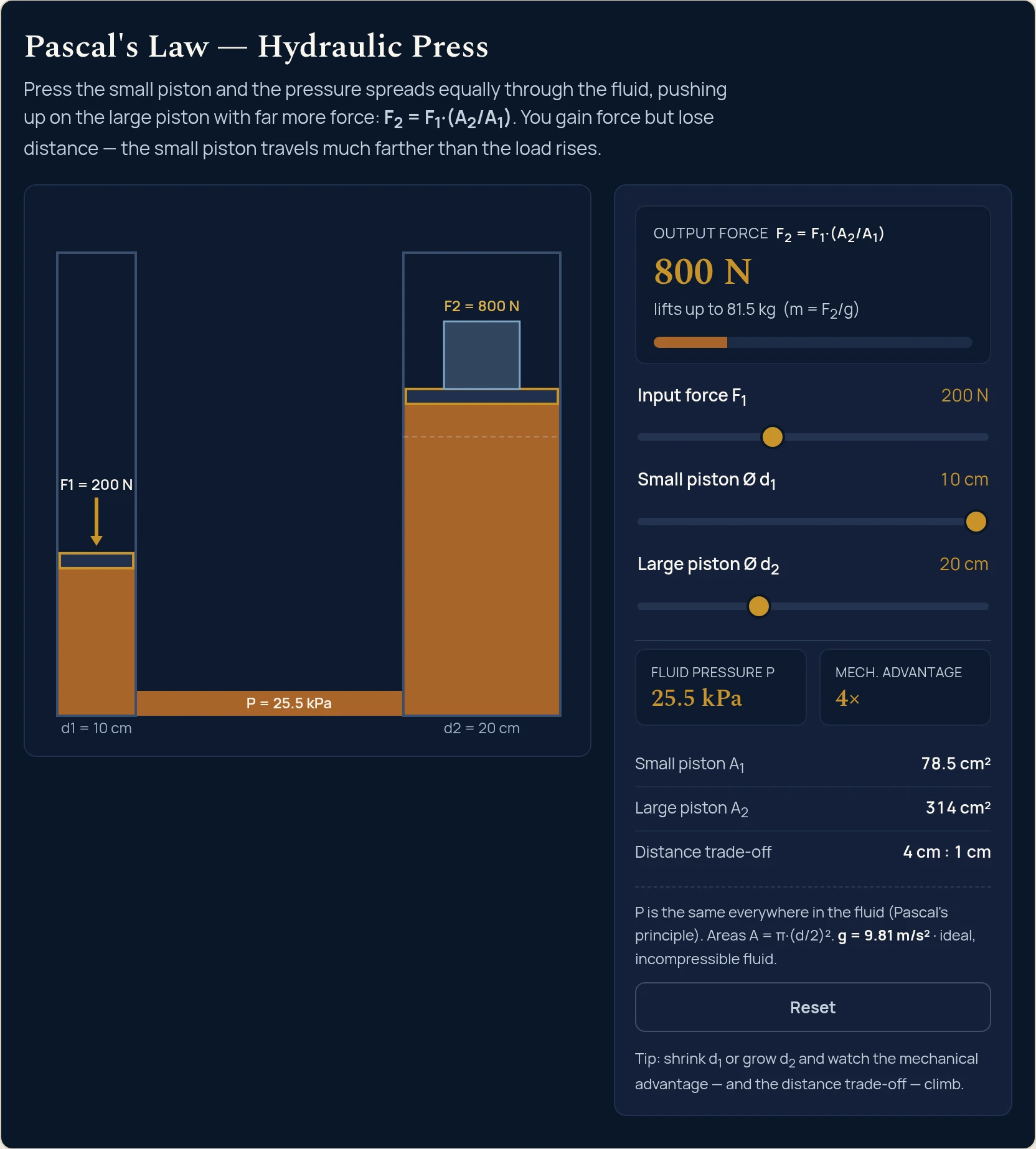
Put numbers to a specific pair of pistons with the Pascal's law calculator, size a real cylinder including its rod side with the cylinder force calculator, or see the same force-for-distance bargain without the fluid in the mechanical advantage simulator. Everything else we build is in the library of physics simulations.
Pascal's law says that pressure applied to a confined, incompressible fluid is transmitted equally throughout it. So the pressure is the same on both pistons of a hydraulic press: P = F1/A1 = F2/A2.
The output force is F2 = F1·(A2/A1) = F1·(d2/d1)². Because a piston's area grows as the square of its diameter, a large piston five times the diameter of the small one gives twenty-five times the force.
No. The large piston moves proportionally less than the small one (A1·s1 = A2·s2), so the work put in is about equal to the work got out — you trade distance for force, exactly like a lever.
The pressure is the same everywhere in the fluid; it is the different piston areas that turn that shared pressure into different forces, since force = pressure × area. A bigger piston, same pressure, means a bigger force.
Because the pressure is set entirely on the input side: P = F1/A1. The large piston has no say in it. Its only job is to decide how much force that shared pressure collects, through F2 = P·A2. In the simulator you can watch this directly — going from a 20 cm to a 40 cm large piston takes the output force from 20 kN to 80 kN while the pressure sits unmoved at 637 kPa.
How far the input piston has to travel for each centimetre the load rises. The fluid is incompressible, so the volume swept by the small piston has to reappear under the large one: A1·s1 = A2·s2. At a 400x mechanical advantage the readout shows 400 cm : 1 cm, meaning a full metre of input stroke lifts the load by just 2.5 mm.
Yes, for the change in pressure, which is what the law is actually about. The absolute pressure at the lower piston is higher by rho·g·h — roughly 8.6 kPa for every metre of hydraulic oil — but any pressure you add at one piston still appears undiminished at the other. In a machine running at hundreds of bar that head term is a fraction of a percent; in a low-pressure system with a tall standpipe it is not negligible.
Because pressure is cheap and area is expensive. Raising the working pressure lets a designer shrink every cylinder, hose and fitting for the same output force, which saves weight and cost. This lab is limited to 500 N pushed straight onto a 2 cm plunger, so it cannot exceed 1590 kPa. A real hand pump puts a lever between your hand and the plunger, and an excavator or press uses an engine-driven pump, which is how they reach 200 to 350 bar.